I fear this is a stupid question because the answer will be obvious when you know it: I expect it is somewhere in the "Programming 101" module, which I missed.
But any decent discussion forum has a policy that there are no such thing as stupid questions so here we go...
I'm using an ATtiny13 and I have a section of the code where I want to send it to sleep and have it wake up periodically.
That works fine, but I don't want it to do that all of the time, so I need to turn the watchdog interrupt off.
I think I need to set the bits in one of the registers and I don't understand the syntax to do it.
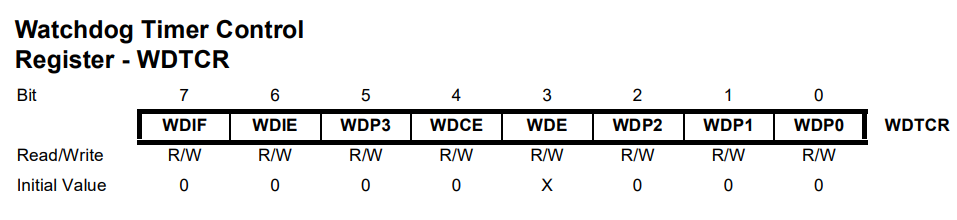
The example code from the ATtiny core says:
WDTCR = _BV(WDTIE) | _BV(WDP2) | _BV(WDP1);
And I know that that is setting the WDTIE, WDP2 and WDP1 bits in the WDTCR register to 1... Well, I say "Know", it is what I think they are doing, but I don't understand how they're actually doing it.
But how do I clear those bits? Or otherwise turn the watchdog timer off?
when you say 1 in C++, the compiler allocates an int (so on a 8 bit platform it would be two bytes and 4 bytes on a 32 bit platform) and thus the binary representation of 1 (say on 8 bit platform) is 00000000 00000001
if you shift that memory by 3 position left you get 00000000 00001000 hence putting the 1 at the bit 3 position (bits are numbered starting at 0 for the least significant bit)
if you assign that value into an 8 bit register (or any byte variable), C++ will truncate the value and only 00001000 will be used for initializing the register
well if you think it does not matter, as the only thing you did was to put 0 into 5 bits and 1 into 3 bits, the easiest way to remove all the 1 is WDTCR = 0;
they store the SREG register into oldSREG, suspend interrupts do some bitwise stuff and then just restore the SREG as it was before, which will activate interrupts again.
Setting all of the bits with '='. This sets the specified bits to 1 and the unspecified bit to 0: WDTCR = _BV(WDTIE) | _BV(WDP2) | _BV(WDP1);
Setting some bits to 1 and not changing the others with "|=" (a shortcut for "x = x | "). This sets the specified bits to 1 and leaves the unspecified bits unchanged: WDTCR |= _BV(WDTIE) | _BV(WDP2) | _BV(WDP1);
(shortcut for WDTCR = WDTCR | (_BV(WDTIE) | _BV(WDP2) | _BV(WDP1));)
Setting some bits to 0 and not changing the others with "&=" (a shortcut for "x = x & "). This sets the specified bits to 0 and leaves the unspecified bits unchanged: WDTCR &= ~(_BV(WDTIE) | _BV(WDP2) | _BV(WDP1));
(shortcut for WDTCR = WDTCR & ~(_BV(WDTIE) | _BV(WDP2) | _BV(WDP1));)
Note: '~' turns all the 1s to 0s and all the 0s to 1s.
There is no operator that will set some bits to 1, some bits to 0, and leave some unchanged. You have to do it in two steps.
Your code may be easier to follow, but that technique will NOT work for some operations. The reason is that it evaluates to three separate read/modify/write operations, so the bits change one at a time. The 'bureaucratic jargon' changes all three bits in the same operation.
This becomes important if you need to do something like enabling the watchdog timer. Changing the WDE bit requires that both the WDCE and WDE bits have a 1 written to them in the same operation.
Lots of good discussion, but I didn't see this addressed so here goes.
You don't need to feel bad not knowing what it's doing because the _BV macro is not something you would find in any "Programming 101" book. While JML showed you what it meant, he didn't show you where it came from. It is not a general feature of C or C++.
This a macro that is defined in the underlying AVR-libc library that Arduino is built on top of. Specifically, it comes from the avr/sfr_defs.h file, line 208.
#define _BV(bit) (1 << (bit))
That file contains lots of macros that you don't normally see since they're mostly used "under the hood" so to speak. Have you ever wondered how your program knows what WDTCR is? Or where the WDTIE is defined? The programming language has no inherent knowledge of these things on its own. You can find that in the include/avr folder. Every different AVR device has it's own header defining all the register and bit names for that particular device (an Uno uses iom328p.h). In there you can see it define all the bit names and the register names using the SFR macros from the sfre_defs.h file.
It is worth noting that this method of defining registers and bits is a convention specific to this library for AVR devices. Other microcontrollers may use a completely different convention even if they use the same programming language. Even other Arduinos that aren't AVRs (like the Due) don't have this macro.