Take 2, DC motor control

Hi,

Not very knowledgeable with this stuff, be kind please. :grin:

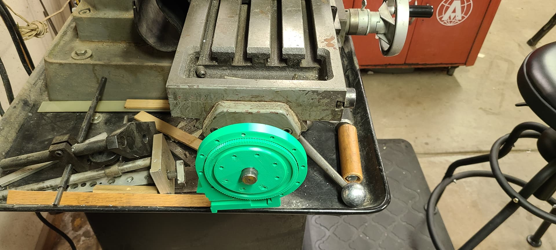
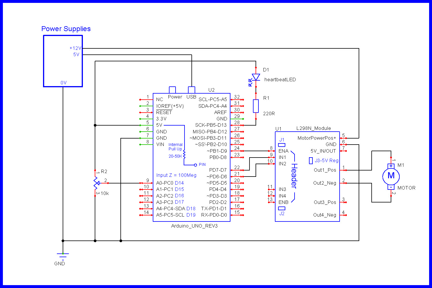
I have a DC window motor, L298N H bridge motor control board, an UNO, a volume knob thing (potentiometer), power, and a dream...

I would like to turn the knob and have the motor increase speed as I turn the knob in one direction. I would like the motor to return to 0 rpm as I turn the knob back the other way.

Could I get assistance with (everything) the code and wiring?

Thanks!

Jim

Always show us a good schematic of your proposed circuit.
Show us a good image of your ‘actual’ wiring.

At the moment, I have none.

I've tried using various software to set it up but none have the L298N board.

Do you need to reverse the motor’s rotation ?

Yes but I planned to use a single throw double pole switch to flip the polarity. Ideally the pot would be at zero half way thru its stroke and turning the knob keft or right would result in fwd/back on the motor. But that is way above my level fer sure.

  • So you want the motor stopped when the potentiometer is center position.

  • Motor goes CW when turned CW

  • Motor goes CCW when turned CCW

  • Motor speed increases the more the potentiometer is turned

? ? ?


Will you be using 12V to power the motor ?

Yes, yes, yes hahaha

I was going to use a stepper motor fitted to a worm driven slew gear. I couldn't figure it out and didnt get the help I needed on this forum (too high level). So, applying the kiss principle, backing up to simple dc motor etc.

What is the resistance of the motor ?

What is your experience in C++ software ?

What is your hardware experience ?

Why are there wires on the motor driver already ?

Ultimate goal is to power feed a mill table back and forth. 2 pics.


What is the resistance of the motor ?

What is your experience in C++ software ?

What is your hardware experience ?

Why are there wires on the motor driver already ?


Are you sure the that motor can turn the controls ?

1 Like

No clue. I connected the multimeter up set to ohms, returned 1.4M Ohms.

C++ knowledge very low. I have copy/pasted and uploaded code to my UNO boards. Ive read thru the code to try and understand. I understand from a very high level what the commands are saying but not how to manipulate them to my needs.

Hardware exp is great. Most of this is from the CNC router I built from scratch following someones build plans.

Wires are there from my failed solo attempts.
The motor has pos/neg leads, the pot has 3 wires, otherwise consider there to be no wires.

Won't know if it'll work til I try. From there, I can 3d print various gearing to get me over the hump.

Including reintroducing the slew gear setup.

If you measured the motor coil resistance with the meter leads connected to the two motor wire leads, 1.4M implies the motor is bad.

Hahahaha, sigh. The motor is good. I connected it straight to 12v and it runs fine. How else should I check the resistance you seek?

Do you know how to measure resistance with a DMM ?

If so, try again.

First make sure you get 0 ohms when the test leads are shorted together.


EDIT

How will you be powering the Arduino ?

1 Like

Shorted leads no bueno. Apparently those leqds were bad. Switched leads. Shorted together 0.3 ohms. Connect to motor, 0.8 ohms. Using Fluke 77.

I have a 5v power source for UNO and a 12v separate source for the motor.

Switched meters to Cen-tech. Shorted = 0, motor =0 too.

Does this schematic make sense to you ?

1 Like