Yes
Why the led and what do the extra resistors do? Looks straightforward, thanks!
Had to look up symbol for pot. So there's one extra resistor for the led.
It toggles every 500ms. A LED needs a resistor.
It gives a visual indication to the user that the sketch is running.
BTW
J1 in the schematic would be removed.
What software did you use for that schematic?
Arduino pin 9 is the speed control pin.
Arduino pins 7 and 6 are the motor direction pins.
The potentiometer is read, this reading is used to make pin 9 output a PWM signal.
Levels on pin 7 and 6 determine CW or CCW rotation.
The schematic program is no longer available, however, KICAD and easyEDA are free schematic drawing programs.
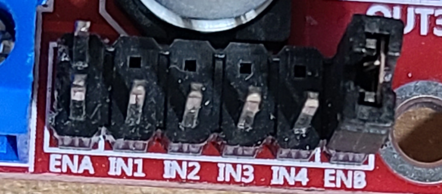
ENA would be removed, you will not be needing ENB as it is for the 2nd channel.

Do you have a wire (common) between Arduino 0V and L293N motor driver 0V ?
Is the center of the potentiometer going to A0 ?
Arduino 5V and 0V needs to be on the outer most potentiometer terminals.
Ground? No
-
Is the center of the potentiometer going to A0 ?
-
Arduino 5V and 0V needs to be on the outer most potentiometer terminals.
-
Look at the schematic, a common is needed between the Arduino and the motor driver.
A0 - pot - middle wire check. 5V and GND, check.
Can I run a wire from GND on UNO to the GND power input on L298N? Else, no other GND points on L298N that I see.

NoOOOOoOOO!!!!!!!!! Hahahahah stay! I need the final pieces....hahahhaa
Sigh
Hey, thanks very very much for helping me tonight! Really appreciate it!
Thats the spot i was referring to but no male pin sticking up, have to add a wire.
Don't know, sorry
Hi, @Lskuared
You say it runs on 12V OK, do you have a DMM that can measure AMPS.
If so check how many AMPS the motor draws when it runs on the 12V supply.
Then check the current rating of your motor controller.
Do this before anything else.
Tom... ![]()
![]()
![]()
![]()
PS. Note that that will be the free running noload current, not the current it will draw underload.
2.4 amps on 18v. I'll check tomorrow on 12v.
Jim, you might find this of interest...
https://www.model-engineer.co.uk/forums/postings.asp?th=166690