First of all, Hi and thanks for all the insights.
A frien of mine neeed to activate a relay, on a color change on a monitor, no porblem there, there are 3 mayor colors; green for pass, black for wait (non activate) and red (non active).
Im trying to use an TCS230 sensor for the color readings.
At first when on:
This simple example, and the sensor star to works, read some values and stuff.
when I tried to read some specific color, the fun begun, and shortly I realize I migth need a very good Lib for the Job.
Fortunately, I fount this one:
It has many interesting features, like the fact for start, that has a "calibration", for read more accurately.
And the capacity for read color and label them for the use in the program.
An here is were I need some of you help.
I tried to wire like the previous example, and in the begging I was very unsure, because in the first example of circuit today they use 6 wire, and in the library code they only mention 3 wires.
Long story short:
The sensor has to be wired correctly, and the sensor has a hardware problem.
This are the tips I can found use the web:
1.- In the use of the library, the sensor might be modify, (There is a PDF on the Library download folder, more details in there).
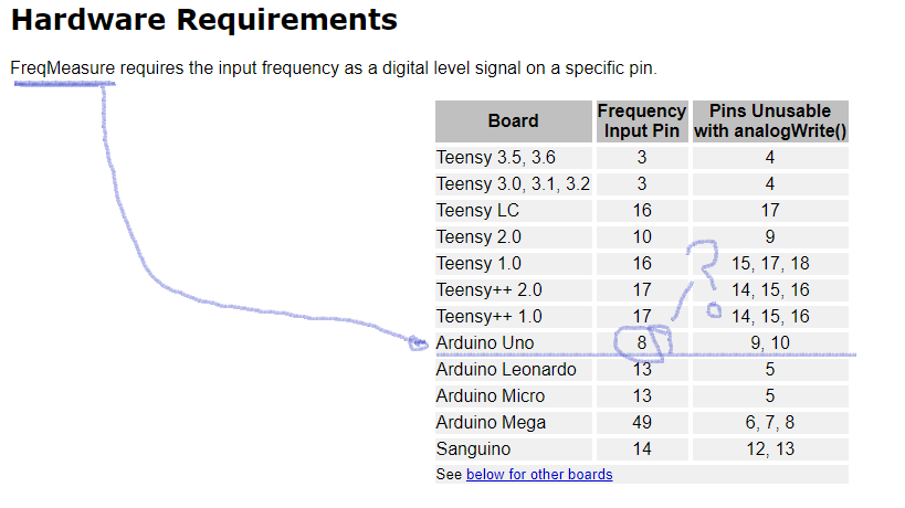
2.- This is a library uses another, called FreqCounter, more on this on This thread and for the use of this library, you have to check the rigth hardware pin to be used (as not all of them are usable for this purpose). There is a
I pin the sensor as follows:
S0 - VCC
S1 - VCC
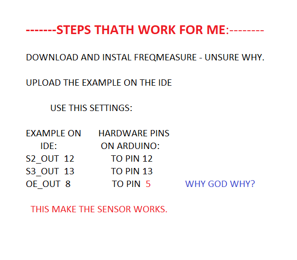
OUT - PIN 5
S3 - pin 10
s4 - pin 11
vcc - vcc
gnd -gnd
I tried the calibration, and I get color is RGB[0,0,0]
So, I modify the sensor, tried again and still get the same error.
I search and some people were correcting they errors by choosing the rigth output pin, in this case the 5, (Im using arduino UNO).
this is the code;
// TCS230 sensor calibration and color readings
//
// Input and output using the Serial console.
//
#include <MD_TCS230.h>
#include <FreqCount.h>

#define	BLACK_CAL	0
#define	WHITE_CAL	1
#define	READ_VAL	2

// Pin definitions
#define  S2_OUT  11
#define  S3_OUT  10
#define  OE_OUT  5    // LOW = ENABLED

MD_TCS230	CS(S2_OUT, S3_OUT, OE_OUT);

void setup()
{
  Serial.begin(57600);
  Serial.print(F("\n[TCS230 Calibrator Example]"));

  CS.begin();
}

char getChar()
// blocking wait for an input character from the input stream
{
	while (Serial.available() == 0)
		;
	return(toupper(Serial.read()));
}

void clearInput()
// clear all characters from the serial input
{
	while (Serial.read() != -1)
		;
}

uint8_t fsmReadValue(uint8_t state, uint8_t valType, uint8_t maxReads)
// Finite State Machine for reading a value from the sensor
// Current FSM state is passed in and returned
// Type of value being read is passed in
{
	static	uint8_t	selChannel;
	static	uint8_t	readCount;
	static	sensorData	sd;

	switch(state)
	{
	case 0:	// Prompt for the user to start
		Serial.print(F("\n\nReading value for "));
		switch(valType)
		{
		case BLACK_CAL:	Serial.print(F("BLACK calibration"));	break;
		case WHITE_CAL:	Serial.print(F("WHITE calibration"));	break;
		case READ_VAL:	Serial.print(F("DATA"));				break;
		default:		Serial.print(F("??"));					break;
		}

		Serial.print(F("\nPress any key to start ..."));
		state++;
		break;

	case 1:	// Wait for user input
		getChar();
		clearInput();
		state++;
		break;

	case 2:	// start the reading process
		CS.read();
		state++;
		break;

	case 3:	// wait for a read to complete
		if (CS.available())
		{
			sensorData	sd;
			colorData	rgb;

			switch(valType)
			{
			case BLACK_CAL:
				CS.getRaw(&sd);
				CS.setDarkCal(&sd);
				break;

			case WHITE_CAL:
				CS.getRaw(&sd);
				CS.setWhiteCal(&sd);
				break;

			case READ_VAL:
				CS.getRGB(&rgb);
				Serial.print(F("\nRGB is ["));
				Serial.print(rgb.value[TCS230_RGB_R]);
				Serial.print(F(","));
				Serial.print(rgb.value[TCS230_RGB_G]);
				Serial.print(F(","));
				Serial.print(rgb.value[TCS230_RGB_B]);
				Serial.print(F("]"));
				break;
			}
			state++;
		}
		break;

	default:	// reset fsm
		state = 0;
		break;
	}

	return(state);
}


void loop()
{
  static uint8_t	runState = 0;
  static uint8_t	readState = 0;

  switch(runState)
  {
  case 0:	// calibrate black
	  readState = fsmReadValue(readState, BLACK_CAL, 2);
	  if (readState == 0) runState++;
	  break;

  case 1:	// calibrate white
	  readState = fsmReadValue(readState, WHITE_CAL, 2);
	  if (readState == 0) runState++;
	  break;

  case 2:	// read color
	  readState = fsmReadValue(readState, READ_VAL, 1);
	  break;

  default:
	  runState = 0;	// start again if we get here as something is wrong
  }
}
But I cant figure out, were is the error.
Any help will be appreciated.
-Alex.