Hi there,
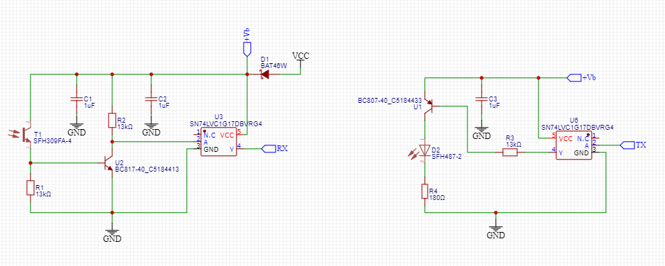
The following is a part of an electric meter reader project.
Since there is no visible indication, how can I test the TX and RX is working?
Hi there,
The following is a part of an electric meter reader project.
Since there is no visible indication, how can I test the TX and RX is working?
You can use your cell phone camera to see the IR light from the transmitter.
Just send some data and you should see it blinking
If the transmitter is working, you can connect an LED ard resistor to the RX pin and you should see it blink.
If you connect the TX to ground the IR LED should stay on, if you connect it to +Vb it should go off
. . . and with an IR based TV remote control and a led (with series resistor) between RX and ground, you can also test the receiver part.
LED is fully lit, not blinking when I point a TV remote.
I'm seeing full voltage 4.68v across T1 pins,which is the same voltage measured at D1.
See post #2
Probably will not work with a TV remote.
That is to be expected. This is because the carrier frequency is usually around 38kHz for a TV remote control. The human eye will perceive this as a solid signal. Important is that the led is off when no button is pressed on the remote control and, when a button is pressed, the led lights.
How, incidentally, are you measuring the voltages. With multimeter or an oscilloscope ?
Even if it could work with a TV remote, you have that backwards.
OK. I think I see what you are doing. It appears to be an interface for something like this: IEC 62056 - Wikipedia .
You should be able to test your device using a so called loopback test with your Arduino. Something like this: https://support.arduino.cc/hc/en-us/articles/360020366520-How-to-do-a-loopback-test where instead of a simple wire connecting TX and RX you insert your device.
Can you supply more details of the meter you are interfacing with?
@dinesha77
see post #2 for testing
It won't work with a TV remote
My device, not seing anything through the phone camera. However, TV remote I can see.
Then the transmitter is not working
IR LED is not On.
could it be the IR LED is faulty?
With Tx connected to ground check the voltage on D2 anode, the side that connects to U1 in your schematic
Btw, now VCC is 3.3v.
D2 Anode side read 3.0v, same voltage at the D1 Cathode side.
When I remove the TX from GND, voltage at D2 Anode becomes 1.6v.
I'm sure it was designed for 5V but may also work with 3.3V
D2 Anode side read 3.0v, same voltage at the D1.
That means the transistor is turned on and the IR LED has voltage.
Now check the voltage on the cathode. It should be around 1.5V if you are using 3.3V for Vcc.
If it's near zero or 3.0V then the IR LED may be bad or there is a bad connection/solder joint somewhere.
It reads as 1.76v
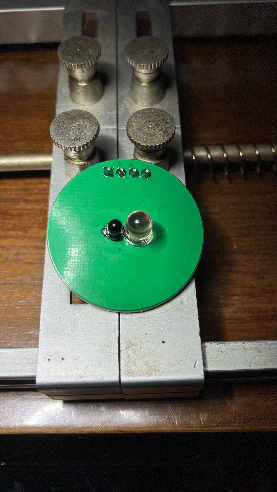
I can see the light through the phone camera. Earliyer I was checking this during the day time, now it is night time. However, brightness is very low. Is that normal? I tested with 5v VCC, same brightness.
So the transmitter part is working.
brightness is very low
The current is about 20mA which is low for that IR LED so it will not be very bright
This topic was automatically closed 180 days after the last reply. New replies are no longer allowed.