from china and i cannot even figure out if it will output ANYTHING,
my original application is to use it as an INTERNET RADIO STREAMER but at this point i would be happy to even hear a BIP sound as an output
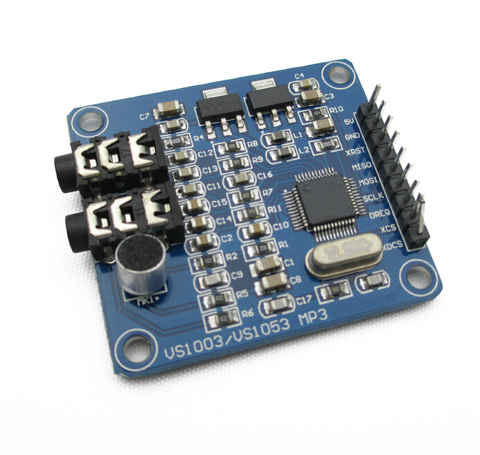
dont even know which P.L connector is line out and or line in.
i dug up the forum and the googled many combinations but seems that i cannot find a simple thing,
a woking SIMPLE SKETCH, that will test the MP3 output of this module, and confirm that the board is working or defective, ALONG with a proper PIN connection diagram for arduino UNO
i have several concerns,
does this board require any protection on its input/output pins?
can it be damaged by being connected to PIN13 > SCLCK and accidentally runing an old "flash the LED" program that outputs "full power" on this pin?
THANX FOR ALL HELPERS.
i think arduino is a very useful tool when it comes to some kind of automation,
wish things would be more clear on the manufacturers side...
My project is a bet different then yours. I want to build a device that plays 3 specific mp3 files based on which button you click. But getting started with controlling the sound up would just be great.
I bought two of these type of boards way back in 2013 and never managed to get them working despite trying all the libraries and source code that I could find at the time.
After a long break I decided to pick them up again and managed to get as far as some drums and instruments via the MIDI part of the chip. Buoyed with that success I tried for MP3s and spent several days on and off trying most of the various libraries again, convinced I would stumble upon the magic combination.
It was this post LCsoft VS1053 MP3 module - Bajdi electronics that finally gave me success. Initially I shorted the two pins with the end of a jumper wire held against them and I suddenly had music.
Further reading in that post there is a section that shows how to change the mode of the chip after boot rather than shorting the two pins (I do not have a small enough bit to solder the two pins for a permanent solution) so I inserted the appropriate code into the initialisation/startup function (I did it in both Adafruit and SparkFun libraries) and AT LAST... MUSIC
Although I got my VS1053 working by lodging a piece of wire between pins 33 & 34, I did not think my soldering skills were adequate for making it a permanent solution. Fortunately it turns out there is another solution.
On the VLSI website someone has asked if there is way to exit midi mode. Appraently it is possible to initiate a software re-boot and over-ride the state of pin 34. This is the method described:
“You can detect RTMIDI mode after hardware/software reset by checking AUDATA. If you see 44100/44101, RTMIDI has been activated, and you can write GPIO_DDR=3 and GPIO_ODATA=0, then give software reset to boot into normal decoding mode.”
I have tried it & it works. For information the address of GPIO_DDR is 0xC017 and the address of GPIO_ODATA is 0xC019.
My project is to build a module that connects to a PA system and is controlled via HTTP requests so that I can make automated announcements for train departures.