Hi, can you help me please, i try to make an automotive rpm tachometer, All perfect, but, when is near engine or connected to ckp sensor, the tft screen colapse but the esp32 still working fine. its some kind of electromagnetic field noise.
any help is regard. thanks


The automotive electrical system is fraught with noise. Noise being high voltage spikes, RF signals especially and lower frequencies.
I assume you only have two inputs, power and RPM pulse. First thing to do is to tidy up the wiring trying to eliminate any long wires.
Where is the power coming from? Is the signal ground to the vehicle the same as the power ground?
You will need to filter the incoming RPM input pulse. Is the incoming pulse limited to 3.3Volts? Perhaps a schematic of at least the ESP32 power and signal input. I don't think the LCD is of concern at this point but you should tell us where the LCD gets its power.
1 Like
Hi, @pakotzintote
Welcome to the forum.
Can you please post a copy of your circuit, a picture of a hand drawn circuit in jpg, png?
Hand drawn and photographed is perfectly acceptable.
Please include ALL hardware, power supplies, component names and pin labels.
What is it, can to post a link to spec/data?
Thanks.. Tom.... ![]()
![]()
![]()
![]()
1 Like
think I would tend to simplify the wiring by moving to a TFT with an onboard ESP32
how do you count RPM, e.g. use the ESP32 Pulse Counter (PCNT)?
1 Like
hi every one, thaks for replys,
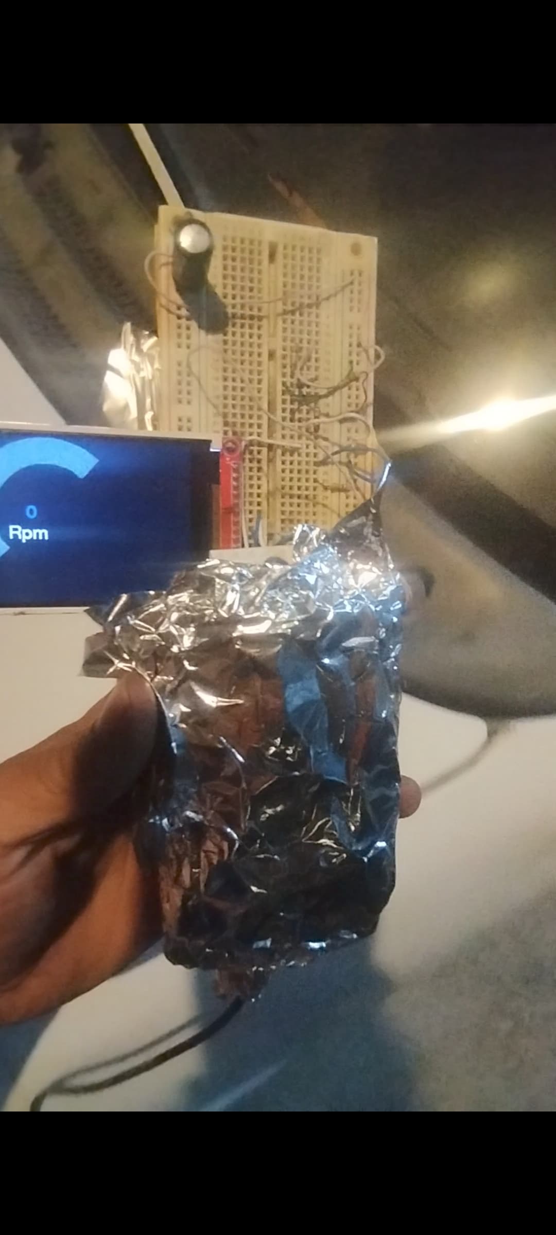
the fail apear even totaly disconnected from any car signal or supply, just happen when getting near of car battery
It doesn't really distinguish the power supply, it always fails: when a 12v to 5v adapter is connected to the car's cigarette connector, when I use a 110ac to 5v regulator or even using batteries
this is the ckp signal, its provided by ckp sensor

this is the wave in oscc

the code use external interruption on gpio 18, it dont use PCNT
and the code
#include "FONDO.h"
#include <TFT_eSPI.h>
TFT_eSPI tft = TFT_eSPI();
TFT_eSprite gaugeBack = TFT_eSprite(&tft);
int AdcValor = 0;
int OffsetArc = 45;
int AnchoArc = 20;
#define RingColorArc 0x455a  //0x455a
#define RingColorKnob 0xc2c4
const int OutterRArc = 69;
const int InnerRArc = 58;
const int pinAdc = 32;
TaskHandle_t Task1_Dibuja;
TaskHandle_t Task1_Calcula;

const int pinPulso = 18;
const int toggle = 19;
byte NumDientes = 58;
uint pulsos = 0;
uint inicioCiclo = 1;
uint finCiclo = 1;
uint tiempoMedicion = 1000000;
uint tiempoCiclo = 1;
float rpm = 1;
uint vueltas = 0;
byte factor = 1;

void IRAM_ATTR INTDiente() {
  pulsos += 1;
  //digitalWrite(toggle, !digitalRead(toggle));
}

void setup() {
  Serial.begin(9600);
  Serial.println("inicio");
  analogReadResolution(10);
  tft.begin();
  tft.setRotation(1);
  tft.fillScreen(TFT_BLACK);
  tft.setSwapBytes(true);
  tft.pushImage(0, 0, 320, 240, img1);
  xTaskCreatePinnedToCore(Task1FunctionDibuja, "Task1FuncDibuja", 80000, NULL, 0, &Task1_Dibuja, 0);

  pinMode(pinPulso, INPUT);
  pinMode(toggle, OUTPUT);
}

void loop() {
  attachInterrupt(digitalPinToInterrupt(pinPulso), INTDiente, RISING);
  inicioCiclo = micros();
  delay(1000);
  detachInterrupt(pinPulso);
  tiempoCiclo = micros() - inicioCiclo;
  rpm = (((float)pulsos / (float)NumDientes));  //*60, pero son 2 segundos
  rpm = rpm * 60;
  Serial.print("pulsos= ");
  Serial.print(pulsos);
  Serial.print("  dient= ");
  Serial.print(NumDientes);
  Serial.print("    tiem= ");
  Serial.print(tiempoCiclo);
  Serial.print("    rpm= ");
  Serial.println(rpm, 5);
  pulsos = 0;
  attachInterrupt(digitalPinToInterrupt(pinPulso), INTDiente, RISING);
}


void Task1FunctionDibuja(void* parameter) {
  for (;;) {
    inicioDibujo = millis();
    while (millis() - inicioDibujo < 1000) {}
    //rpm=(60000/tiempoCiclo);
    AdcValor = (rpm * 180) / 6000;
    tft.setTextSize(4);
    tft.setCursor(150, 194);
    tft.fillRect(150, 194, 200, 30, 0x1ae4);
    tft.setTextColor(TFT_WHITE);
    tft.println(rpm);
    if (AdcValor > 1) {
      tft.drawSmoothArc(141, 127, OutterRArc, InnerRArc, OffsetArc, AdcValor + OffsetArc, RingColorArc, RingColorArc);
      tft.drawSmoothArc(141, 127, OutterRArc - 2, InnerRArc + 2, AdcValor + OffsetArc, AdcValor + OffsetArc + AnchoArc, RingColorKnob, RingColorArc);
      tft.drawSmoothArc(141, 127, OutterRArc, InnerRArc, AdcValor + OffsetArc + AnchoArc, 180 + OffsetArc + AnchoArc, RingColorArc, RingColorArc);
    } else {
      tft.drawSmoothArc(141, 127, OutterRArc, InnerRArc, AdcValor + OffsetArc + AnchoArc, 180 + OffsetArc + AnchoArc, RingColorArc, RingColorArc);
      tft.drawSmoothArc(141, 127, OutterRArc - 2, InnerRArc + 2, 0 + OffsetArc, OffsetArc + AnchoArc, RingColorKnob, RingColorArc);
    }
    //vTaskDelay(400);
  }
}
thanks
this is the minimal circuit only 5v usb power supply, spi conected as this
#define TFT_MISO 12
#define TFT_MOSI 13
#define TFT_SCLK 14
#define TFT_CS 15 // Chip select control pin
#define TFT_DC 2 // Data Command control pin
#define TFT_RST 21 // Reset pin (could connect to RST pin)
//#define TFT_RST -1 // Set TFT_RST to -1 if display RESET is connected to ESP32 board RST
and gpio 18 to recibe ckp signal

Thanks, this is the answer, the circuit has an input free with cable, i Guess actings like antena
thing to do is to tidy up the wiring trying to eliminate any long wires.
Thanks, this is the answer
simplify the wiring
Thanks, your tip helpme too much
This topic was automatically closed 180 days after the last reply. New replies are no longer allowed.