The art of battery sipping

I am creating a device based on a ATtiny85 MCU that will be powered by a coin cel battery that I wish to last for many months. The work the device is expected to do is to wake up when a pot value changes, transmit (by nRF24l01) the analog value sensed from the pot, and then go back to sleep.

The schematic I have in mind (below) has a pot (RP1) with a pin at ground, middle pin as sweeper to the ATtiny, and the final pin at VCC, basically a 10kohm battery leak. I can raise the value of the pot to make it drain the battery slower, but the higher the impedance the more it will be effected by RFI/EMI causing false triggering, waking the radio, etc... killing the battery.

Is there some sort of extremely low powered comparator I can use to wake the MCU? Or perhaps ditch the ATtiny for an MCU with more pins so I can use the internal comparator (that is, of course, if "wake on internal comparator" is such a thing ).

Thanks everyone for reading / input / advice / critiquing... It's all appreciated!

Dan
San Jose, CA

CR2023

― ? ―

Even if you use a comparator, I feel that it is difficult to detect that the POT has rotated.
This is because it is necessary to retain the "previously transmitted voltage".

Probably, I think that I will wake up from sleep on a regular basis, acquire the POT value with the ADC, check if it has changed from the value acquired last time transmitted it, and if changed then need transmit it.
In that case, the current consumed by the POT can be reduced by connecting the POT to the port instead of VCC and passing the current only when measuring with the ADC.

Batteries larger than coin batteries may be required depending on the polling intervals required.

I'm sure it 2032 :wink:

1 Like

Hi,
Have you breadboarded this circuit to see if your proposal works.
I am not sure the CR2023 will be able to provide the pulse energy for the NRF when it transmits.
Have you measured the idle current of the NRF.

Features and Specifications

  • Lithium Coin Cell
  • Nominal Voltage: 3.0 Volts
  • Maximum Current: 0.19A
  • Non - Rechargeable Disposal battery
  • Typical Capacity: 240 mAh @ 20°C 15kΩ Load
  • Service Life: ~720 Hrs @20°C 15kΩ Load
  • Typical Weight: 3.0 grams (0.10 oz.)
  • Operating Temp: -30C to 60C
  • Self-Discharge: ~1% / year

What is your project, is the pot going to be the actual sensor or is there another piece of hardware that replaces it ?

Tom.... :smiley: :+1: :coffee: :australia:

It's a bit harsh on coin batteries, but it should work.
But I think probably not fit the OP's required lifetime. :expressionless:

With proper usage the nRF will consume negligible current compared to the MCU.

And the current spike for transmitting is easily covered by a capacitor.

And to reduce current consumtion of the pot connect it to MOSI instead of Vcc.

It would be nice if you can utilize the IRQ pin from the NRF to signal the MCU, so you don't have to "poll" it, and the MCU can stay in sleep mode. The NRF has multiple power modes so you can certainly keep it in POWER_DOWN until you have to transmit something.

I guess if you switch to attiny84, you might be able to use the internal comparator to wake the MCU from sleep. You would need to use some high-pass filter on the pot output to allow the comparator to detect when a change in the pot setting occurred and exceeds some threshold you could set with a trim-pot. But you would need to detect a change in either direction, and I'm not sure how that could be achieved.

Use a 1M pot and add 10nF or so between wiper and ground to provide a stable and low-impedance source for the on-chip ADC to sample. A 1M pot will drain 3µA which is pretty negligible, it would take 9 years for this to discharge 240mAh all by itself.

2 Likes

Internal comparator cannnot be used. It needs too much current. Periodic wake up and ADC measurement is the only reasonable way. How quickly is needed to react to the pot change?

Thanks everyone for the input! Power economics is truly an art form!

I have replied to every one of your comments below.

Yep 2032 coin battery. Thanks for pointing out the error.

Chrisknightley

“it is necessary to retain the "previously transmitted voltage"

What I imagined is the “previously transmitted voltage” level could be stored in a capacitor attached to the comparator. When the comparator output toggles (because a difference has occurred) the cap gets recharged via the comparator output (through a diode). Several issues with what I just explained, but it is meant to seed further thought. My attraction to comparators does little to solve the problem if the pot is still bridging the rails.

Chrisknightley

“sleep on a regular basis, acquire the POT value with the ADC, “

Perhaps this will be the end solution. As you point out, the MCU outputs are the only way to interrupt the load of the pot. If polling periodically, the power economics possibly favor using the internal comparator, there is a little dance with the comparator register, but on lay glance, it looks like a couple dozen clock cycles (see Smajdalf comments below - I am wrong about this). Where the ADC takes 13 to 25 cycles per sample, not including the preparatory overhead. That said there is a sleep mode referred to as ADC noise reduction meant to quiet things down during a conversion, which may counterbalance the clock cycle difference between being fully awake. Seems like an advanced, bare metal, hack. —NOTE smajdalf sheds light later - I am probably wrong here….

TomGeorge

“Have you breadboarded this circuit to see if your proposal works.”

No I am looking for a jumping off point. Being a non-EE, I reached out for opinions and insight.

TomGeorge

“I am not sure the CR2023 will be able to provide the pulse energy for the NRF when it transmits.”

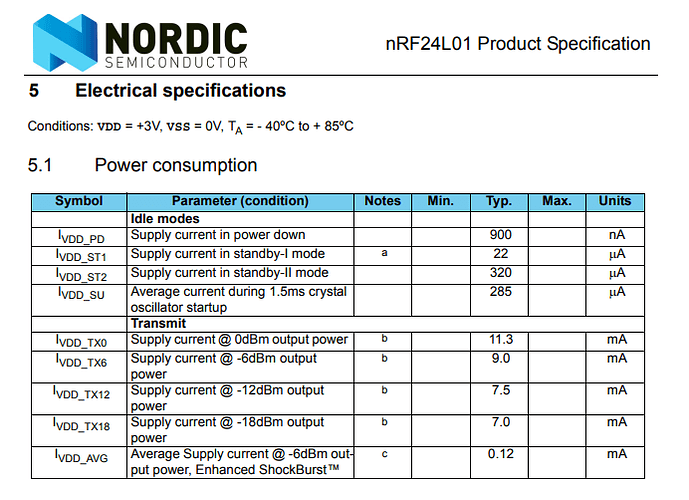
My transmit distance is 2 meters, the nRF24l01 at -18dBm will draw about 7ma. I sourced this information from Table 5.1 of the nRF24l01 datasheet (see chrisnightly’s embed above). Is there another power domain element that I have overlooked?

smajdalf

“to reduce current consumption of the pot connect it to MOSI instead of Vcc.”

That’s interesting! Would this effect the SPI coms? Conditional reassignment? And most importantly, what would the benefit be? Super curious!

hzrnbgy

“utilize the IRQ pin from the NRF to signal the MCU, so you don't have to "poll" it”

I may have misunderstood your idea. The MCU needs to wake on the movement of a local pot. Your concept, if I have understood you properly, would wake the MCU on receipt of incoming radio data.

paulRB

“You would need to use some high-pass filter on the pot output”

“But you would need to detect a change in either direction, and I'm not sure how that could be achieved.”

I am not understanding what role a high pass filter would serve. I was thinking low-pass, to filter emi/rfi. With careful filtering, perhaps a high impedance pot can be used. “...either direction…”
Good point - perhaps bi-polar sensitivity could possibly be achieved by a dual comparator, one blind to positive, one blind to negative. ??

markT

Use a 1M pot and add 10nF or so between wiper and ground to provide a stable and low-impedance source for the on-chip ADC to sample. A 1M pot … would take 9 years for this to discharge …

Thanks mark, I will breadboard this and put it on my scope and hook it to an arduino for testing.

Smajdalf

“Internal comparator cannot be used. It needs too much current. “

My intuition was wrong - is it a software comparator?? I just ctrl-f’d the data sheet, and I am seeing “8-bit comparator”. Further data sheet study awaits me.

Smajdalf

“How quickly is needed to react to the pot change?”

extended dormancy >60 minutes: 100ms
standby: i.e. 1 to 60 minutes since last change: 20ms
active: 5ms (MCU would be idle)

Great comments - thank you so much!!

Dan
San Jose, CA

Perhaps you missed chrisnightley's post in reply #3:

So the pot would not be installed across the rails, but from a GPIO port to ground. Current would flow through the pot only when you need to measure the wiper voltage and you turn on the port, and that would take only a few microseconds once every second or so.

If the ATTiny85 can sleep pretty soundly with just one clock running for the periodic wakeups, the primary determinant of battery life will be what the radio needs. Everything else combined would average only a few microamps.

True, I read chrisnighhtley's point, but forgot to address it . smajdalf alluded to using the MOSI pin possibly in a similar manner. I am hoping he comments on why he suggested that pin. Regarding your mention of the radio - the radio draws 900na in "power-down" mode, - if it can be kept in that mode as long as possible the radio is a low load on the sleeping system.

Thanks for the comment!

Dan

For comparator usage you need to be in Idle sleep and the comparator itself consumes about 100 uA. Crazy high value for continuous usage in micropower application.

To the "MOSI hack": when MOSI is HIGH the pot is powered, consumes power and may be measured. When it is LOW it consumes no power but cannot be used.
From the nRF point of wiev the pot is simply a pull-down that is easily overridden by ATTiny output - no problem. Morover as long as CSN is HIGH the nRF ignores the MOSI completely and is not affected by MOSI transitions needed to measure the pot.

(IIRC for operation around 3 V you need ATTiny85V. Non-V variant needs higher supply.) EDIT: I was wrong, non-V works down to 2.7 V.

He'll be running the Attiny via the 8 MHz internal oscillator so he'll be fine down to 2.7 V

Glue a small magnet to the pot, place one or more reed switches around to be activated by turning the pot, and use that for a wake-up signal.
Alternatively put a metal gear on the pot and a wiper that touches the gear teeth when rotating.

Better still use a rotary encoder and wake up on that!

Yes, that occurred to me too. And I think it should work. The right kind of encoder has both switches open at each detent, so no current would flow when it's idle. Then once the wakeup interrupt occurs, you could disable further interrupts and finish processing the encoder move by polling. Well, there are a dozen ways to handle that, but in any case the encoder would give you more precise control at whatever level of granularity you want.

And since you wouldn't need the watchdog timer running to do periodic wakeups, you could turn everything off and the sleep current would be almost unmeasurable. And of course it would only wake up when someone actually turns that knob.

But I'm not sure the ATTiny85 has enough pins to do all this along with SPI. The ATTiny84 mentioned earlier is I believe a 14-pin chip, available in all the standard packages, including DIP, and might be a better choice. I haven't studied the datasheet, but I assume its sleep current would be in the same ballpark as the 85. I just don't know what IDE support there is for the 84.

Agreed - internal comparator was apparently not part of the low-energy plan. It is out.

Cleverness - Thanks smajdalf!

Noted thanks - I am just as concerned with the point brought up by ShermanP below about the IDE. Arduino and the universe of handy libraries is essential for generalists, such as myself.

Great ideas, a reed switch consumes no power. however in my project, constraints related to resolution, cost, and space... along with the need to use commodity components, make that difficult. BTW - Pulolu makes a motor encoder that appears to be similar in nature to what you are describing.
Pulolu's magnetic encoder.

Do you know of a rotary encoder design that has a near-zero quiescent draw that can toggle a TTL line in response to angular displacement? Such a device would surely be in demand.

I see your point, but it is the switched detent that is the sticking point. The angular resolution I am after, in a package with a diameter of about 20mm, is about .5 degree. At the circumference, if expressed linearly, that would be an inner-detent switch spacing of .08mm (.003"). We are getting the upper realm of thin film deposition, photolithography, etc...

I need to do a deep dive on that. As I mentioned above the Arduino-univeres libraries are an important aid, and accelerator to the development process.

Thanks again to everyone who commented!

Dan
San Jose, CA

If I understand correctly, you're looking for 720 detents per revolution. The encoders I use certainly wouldn't do that, but I would question whether your pot system would either. But with a normal encoder of, say, 30 detents per revolution, you could simply define one detent as representing whatever 0.5 degree represents, and it would take multiple revolutions to represent 360 degrees. There is encoder software that changes what a detent represents depending on how fast the knob is turned. So if you turn the knob slowly, each detent is one step, but if you turn it fast, each detent can be 10 steps, or 20, or whatever, depending on how fast you turn it.

This video has code like that:

https://www.youtube.com/watch?v=2IQFX-KgTpk

Well, I don't know what you're actually controlling with these pot changes, but generally an encoder will give more precise and reliable steps than a pot can.