Theoretical discussion (for now) Arduino as EFI?

disclaimer: when I say EFI I DO NOT mean OBD2. Implementing OBD2 would be unnecessary and an absolute nightmare because of all the EVAP components. I would be shooting for ideally OBD1, but OBD0 could work as well.

This is a 71 Tbird I bought when I was 16, drove for a few months, realized that 500ftlb is cool, but 6mpg is not and just kind of parked it for 12 years. Recently I pulled it from the garage and got it running again.

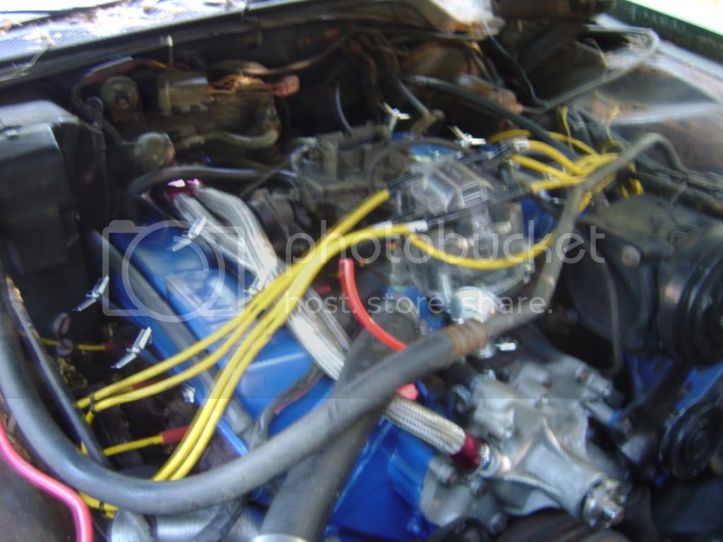
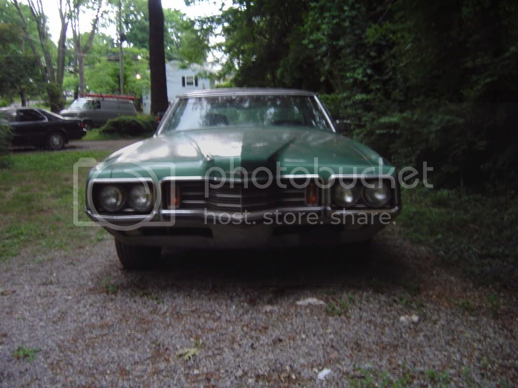
Even though the TBird was a luxury automobile ( cost over twice what a mustang cost) I bought it because it represents everything that is crazy about the USA way of thinking. Its a 21 foot long COUPE with every option available in 71. Power Seats, Power Windows, Locks, Vacuum activated windshield wipers and washers. It weighs over 5,000lb. Did I mention the 429CI engine? :stuck_out_tongue:

I am wondering if it would be possible to use an arduino (maybe a pair) or an arduinomega to run EFI on this car. Currently there is VERY LITTLE available in aftermarket EFI systems for Big Block Fords. There are all kinds of systems for small block ford/chevy and even big block chevy, but big block ford, Nope.

Ford equipped some mid 80s F-250s with EFI 460s. (A 460 is the same as a 429 but with a longer stroke. The 429 can rev much higher) I had originally planned to one day acquire all necessary parts from one of these trucks, and burn a custom eprom for the Ford EEC-IV it would then be equipped with, but I hate EEC-IV.

At first consideration, using arduino for EFI seems impossible, but MOST of what is necessary is actually sitting right there. This car is grandfathered from emissions testing, so it wouldnt have to run perfectly. Id just like it to run on cold days without having to mess with the choke first, and hopefully increase MPG by around 2-4, which would be easy enough to do with a custom ROM map. The vacuum secondary carb that is on there right now is great for idle, but under WOT it goes super rich as most carb'd cars do, so an extra 2-4mpg is very attainable.

I understand (and have a huge collection of parts of) HONDA/ACURA EFI the best. Honda/Acura uses a 28 DIP IC that has a much larger amount of memory than the arduino, but most of it is not used. The standard chip is a 27c256. Usually we replace these with a 29SF512, because it is easily flashable with a Moates Burn2, and the flashable 256 version is obsolete.

For instance, I LOVE Honda/Acura Legends. These cars use 80K in total memory but the way it is divided is very strange. 16K is not on the actual chip. It is in a transmission daughterboard also located in the ECU. Manual cars do not use this daughterboard, so they are only using 64K on the main IC. Thats still twice what the arduino holds, but there is still more to it. The 64K that is on the actual Eprom is divided into 2 sets of maps, one for AUTO cars and one for MANUAL cars. The ECU decides which map it will use based on the presence of a 220ohm resistor that sends high/low to pin 15 which is the bank switching pin. So in reality, there is only 32K being used on the chip. For instance in my car, which is an auto and has a retrofitted 2004 RL motor in it, I have one set of maps running as STOCK and one set that adds between 8 and 10 degrees of total timing advance across the powerband for use with higher octane gas. Then I have 2 wires running to the 220ohm resistor that triggers HIGH/LOW and an SPST switch that flips between the maps.

To create an EFI system like this, you need (at least) 2 charts of values. Both charts have the X axis as MAP pressure (0-5v analog signal) and the Y axis as RPM. The values in table one are total degrees of ignition advance, and the values in table 2 are fuel injector pulse (usually in milliseconds but sometimes its weird.) That actually only occupies half of the 32K being used. The other half is for 2 more sets of tables for LIMP mode when a CEL/MIL is set. I could ignore those 2 charts for now.

Clearly, most of my questions are going to be for the SOFTWARE forum, but hardware comes much more easily for me. I would like to discuss any possible problems on the HARDWARE SIDE ( or if there is going to be a fatal software problem that I will encounter, please mention it, but its not the point of this discussion.)

Lets get out of the way right now - no this would not/will not be easy. Yes, it would probably be cheaper/easier to buy a custom aftermarket setup. (They DO make custom setups for big block Fords but they are almost 2.5 times the cost of a setup for a smallblock.) YES this would take months/possible years to implement. It's about the challenge.

The idea is in my head now, and it's not leaving until it's been proven impossible. If no one can find any hardware reasons as to why it is impossible, it will give me several months to puzzle over it until it gets warm again. If its 100% not possible, I'd prefer to know now so that I can puzzle over other things instead.

Thoughts?

Doh, I knew there was something I was forgetting in my original post. The chip has to be 200ns or faster. A ROM for a car is entirely composed of Hex values. Manufacturers for cars typically frown on editting their roms which is why you usually have to replace the chip with a flashable one (GM and FORD are exceptions - they are even already socketed!)

Turning the Hex values into something meaningful is generally a group effort on a forum. PGMFI.org has managed to decode the Civic/Integra ROM almost entirely. The LEGEND is not a performance car, and while we have the basic values for the tables, there are still lots of other functions hidden in there, and the only way to figure them out is with an engine simulator and datalogging. OR going through the Rom in hex by hand and changing all 32K values one at a time and datalogging the effects. My friend does this part, because he has the equipment and knowledge necessary. This is why I am able to use a program like TunerPro to edit ROMS and chip ECUs, without having a full knowledge of what exactly I am doing. I have a full knowledge of the end result but what happens in between is still a bit of a mystery to me.

I replaced the stock Points distributor in my T-Bird with an HEI unit a while ago, and since it uses a distributor (instead of coil on plug like LEGEND) I can actually do without the timing tables and just use vacuum control for advance.

That leaves Electronic Coolant Temp sensor, Throttle position sensor, MAP or MAF sensor (depending on which I decide would be easier to incorporate) Those are the easy ones, because they are all analog 0-5V.

RPM signal would run straight from the tachometer pin on the distributor (I cant recall what voltage this normally runs at, it may be 12v which would mean I would either have to use a voltage regulator circuit with like an LM117, OR I would have to run the hall effect sensor.

The other possibilty (maybe?) is to use an inductive circuit off sparkplug wire #1, but I dont know enough about inductive output (my timing light does this automatically) to definitively say whether or not that is a possibility.

Injector pulse will be a bit more difficult. Id either have to add a hall effect sensor to determine position (Note: I may be able to use the one in the HEI distributor for this, but if I stuck with vacuum advance, my code would have to accommodate this. Another possibility would be to ignore positioning alltogether and simply use a bank to bank batch fire, but that would be much less efficient at lower RPMs (but a LOT easier to code) On the plus side, injectors take VERY little current to pulse and DO NOT run at 12v. I think the arduino could literally trigger them straight from digital output pins.

The more I think on it, the more it looks like most of my questions are going to be for software forum, but I do have a knack for overlooking the kind of details that make you want to shoot yourself in the face, So i guess Ill wait and see if anyone else finds possible hardware problems before starting a software thread.

Thanks for your input.

There are two limitations that you will run into right off with the AVR:
(1) it's pretty fast for an 8-bit MCU, but may not be fast enough for what you want, and
(2) it is VERY limited in the memory you have to work with.

As Richard mentioned, you would be best to make an estimate of how fast you need the MCU to be and then assess whether an AVR is fast enough for that.

If your motor turns at 6,000 rpm, that's 10 ms per revolution. You have, what, 4 injection events to time in each revolution, so that's 2,500 microseconds for each injector actuation. You probably need to time injection within a couple or 5 degrees. So you have 130 microsecond accuracy requirement in those timings.

Atmel has AVRs that run up to 50 MHz, but I don't think anyone has developed an Arduino platform implementation with this. The fastest Arduinos I know of are 16 MHz. Typical instruction cycle times are 1 to 3 clocks, so you have around 6 instructions per microsecond. Your accuracy requirement is a bit over 750 instructions. Interrupt latency is in the 10 microsecond range -- maybe as low as 5.

It feels to me like it would be doable.

I have no idea what sort of non-timing tasks you will have. If takes 50 ms to read a MAF, O2 electrode or throttle position sensor, that would affect things. I also don't know what sort of calculations or algorithms would be needed, so it's tough to guess if you'll have enough memory.

On AVR RAM is the limiting factor though, and while the "sketch" language does not make it easy to put constants in ROM, this is in fact possible, so relatively large lookup tables -- on the order of dozens of K are feasible.

OK, thanks very much! I didn't understand a lot of what you said (so much more further reading on my part is required) but as I said this would be one of those "couple year" type projects, so I have plenty of time to learn. There is a ton of work just integrating various late model sensors, so perhaps I'll start with that. There is no telling what you really knowledgeable guys can come up with in a year or two, and it may be way more feasible then.

For now I may try to work on turning an arduino into a BCM (body control module) for this car. It was made in 1970 so it uses... zero PCBs and EVERYTHING uses wire. There are probably 300+lbs of wiring in the interior of this car. It even has an analog clock :stuck_out_tongue:

It has sequential rear turn signals (3 bulbs each side, one lights, then half second later the next then half second later the next) and just using an arduino with a delay(500) and power from the turn signal lead would eliminate close to 50 excess pounds!

Back to original topic, another "idea" I had was tapping into the alternator lead prior to the voltage regulator, and trying to use that to infer RPM. These old cars use an external regulator and you will see as high as +18v without it. The problem there is that its way to high of a signal for the arduino to read, and I don't know if it can be stepped down in such a way as to reliably tell the change in RPM through the regulator circuit I'd have to create. thoughts?

Back to original topic, another "idea" I had was tapping into the alternator lead prior to the voltage regulator, and trying to use that to infer RPM.

That probably is not a very good idea for several reasons. Your application is going to need very precise sensor on the crankshaft positioning location at all times anyway, so the same sensor can be used for rpm sensing. Most use some kind of magnetic pickup looking at the flywheel or other hard attached component to the crank.

All in all I think this is a very difficult project for even someone very experianced in electronics and software. Retro fitting a 3rd party system or modifying an existing system is one thing, but a system from scratch design is vey ambitious and carries a very high failure possiblity in my opinion.

Good luck with the T-bird, I've owned both T-birds and mustangs in the past and still consider myself a Ford fan even though I don't presently own any Fords.

Lefty

May not be as cool as coding your own FI solution on arduino, but have you looked into the megasquit system, lots of unusual engines have been FI'ed with it, bbf should be no problem.

May not be as cool as coding your own FI solution on arduino, but have you looked into the megasquit system, lots of unusual engines have been FI'ed with it, bbf should be no problem.

Thats a really great idea! I am not real familiar with megasquirt because usually I am working with cars that have a dedicated ECU, and hacking it is much better (IMO) than piggybacks or megasquirt, but it would be a seriously great application of it on this car! You've sold me on it :wink:

It really will be a couple year project no matter what, because im intent on replacing the heads with some aluminum ones are cars are a far more expensive hobby than electronics. The engine currently weighs over 1200lbs alone. A pair of aluminum heads (even bare) will still set me back over $2K :o Thats why im a recent convert to this.. affordability..

This is exactly what the Megasquirt was built for, old american V8 cars that desperately need EFI.
I think an arduino could probably do it, but it'd be a far more complicated operation then i would want to get into.

A pair of aluminum heads (even bare) will still set me back over $2K

Instead of replacing the heads, have you considered just replacing the carb and doing throttle body injection? It's cheaper, and less fussy about timing (you still need precise pulse width control, but don't have to be exactly in phase with rotation).

HI! I thought about an EFI using arduino and I'm happy somebody is working around it...take a look at this, maybe it could be useful
http://www.google.it/url?sa=t&source=web&cd=2&sqi=2&ved=0CCEQFjAB&url=http%3A%2F%2Fwww.ee.uconn.edu%2FSeniorDesign%2Fprojects%2Fecesd01%2Fsp01_reports%2Fsae_final_sp01.doc&rct=j&q=sae_final_sp01&ei=JfbqTOL1A8eVswbbvcyYDw&usg=AFQjCNHELHC0gMSE2mNTZZgym7DPz0S2Bw

to have an accurate injector timing we need microseconds resolution, i think it could be useful to use port mapping and timer2 features.I don't think you can drive injectors directly from the arduino, I started a project like this on my motorcycle (but I sold it before it was done...) and I used mosfets to drive the Injectors.
then, to start
-we need a tooth gear with a missing tooth region at cyl 1 TDC and a hall effect sensor or a variable reluctance sensor on the crankshaft to read rpm and to know the exact position of the crankshaft.
-we need another sensor on the camshaft to know the firing stroke of the cyl 1 because you can't know it from the crankshaft sensor
-we need a throttle position sensor (just a pot on the throttle valve)
then we can go on with the other sensors.
the main timing chart should come out from rpm/throttle position(x,y), and then be adjusted proportionally by other sensor values like water temp, air temp and pressure...the Ducati EFI works this way
I hope I didn't mess with english... ::slight_smile:

Instead of replacing the heads, have you considered just replacing the carb and doing throttle body injection? It's cheaper, and less fussy about timing (you still need precise pulse width control, but don't have to be exactly in phase with rotation).

TBH, the stock autolite carb works great, and I have a spare Holley 750, and its running an upgraded HEI distributor right now. The problem with the heads is that they were made during a time when leaded gas was readily available, and so compression is set at 11:1. The valve seats have been replaced with hardened seats to accommodate this. The other main objective is eliminating weight. a 5,000+lb full frame coupe drives worse than a boat. I'm a car nut, its my passion as well as my profession, and I have 6 others in various states of repair or perma project :o This is as much about helping me understand the capabilities of the arduino as actually wanting to do it. I am a babe in one area and an old man in the other, so when a discussion is centered around something I understand very well, I gleam a lot more information.

HI! I thought about an EFI using arduino and I'm happy somebody is working around it...take a look at this, maybe it could be useful
Redirect Notice...

to have an accurate injector timing we need microseconds resolution, i think it could be useful to use port mapping and timer2 features.I don't think you can drive injectors directly from the arduino, I started a project like this on my motorcycle (but I sold it before it was done...) and I used mosfets to drive the Injectors.
then, to start
-we need a tooth gear with a missing tooth region at cyl 1 TDC and a hall effect sensor or a variable reluctance sensor on the crankshaft to read rpm and to know the exact position of the crankshaft.
-we need another sensor on the camshaft to know the firing stroke of the cyl 1 because you can't know it from the crankshaft sensor
-we need a throttle position sensor (just a pot on the throttle valve)
then we can go on with the other sensors.
the main timing chart should come out from rpm/throttle position(x,y), and then be adjusted proportionally by other sensor values like water temp, air temp and pressure...the Ducati EFI works this way
I hope I didn't mess with english...

Thank you for the link! Your English is great, much better than my Italian, and my family is from Genoa. ;)The Ducati EFI you describe works just like FORD/GM EFI. They both use a crank sensor with an extra notch to determine TDC, where as the Japanese like to use a secondary TDC sensor, usually incorporated into the camshaft sensor. Then they both reference an X/Y value from a chart of 256 values.