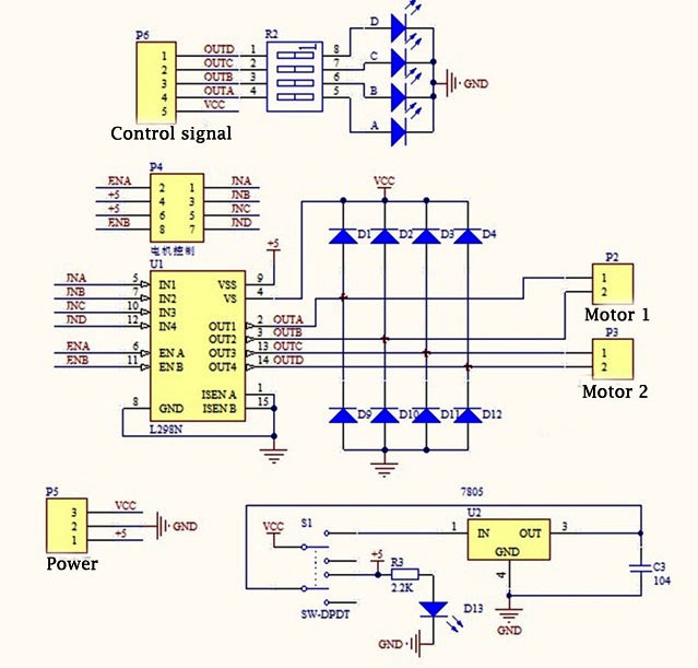
It's actually a single RGB LED and two PWM outputs to control a motor H-Bridge.
i thought that one can monitor the colour of the LED to reconfirm what is being fed to the motor control, fwd/rev (Green vs. Red) and fast/slow (bright/dim)
Is this a bad idea ?
My thinking is that the Arduino pin is sourcing the current, and in parallel that would be split between the PWM and LED - on the LED side it would be dimmer, and with PWM - what counts is the voltage high/low, right - not the current ?
Or am i thinking it backwards, and the PWM will draw the current that it needs and this might overpower the Arduino 20mA limit ?
i guess i gave too much information which ended up being confusing.
it really is just a general situation of connecting TWO output/devices to ONE Arduino (Uno) pin.
so it is simply analogWrite(PWMpin, PWMvalue); - BUT, __two__ output devices, 1) an LED, and 2) a motor module will receive and use this SAME PWMvalue - on the SAME wire.
ElCaron:
Sure. How do you think the onboard LED works?
i see, ok, great !
ElCaron:
Just mind the maximum current from the pin.
yep - that is indeed what i want to determine.
so, following first principles;
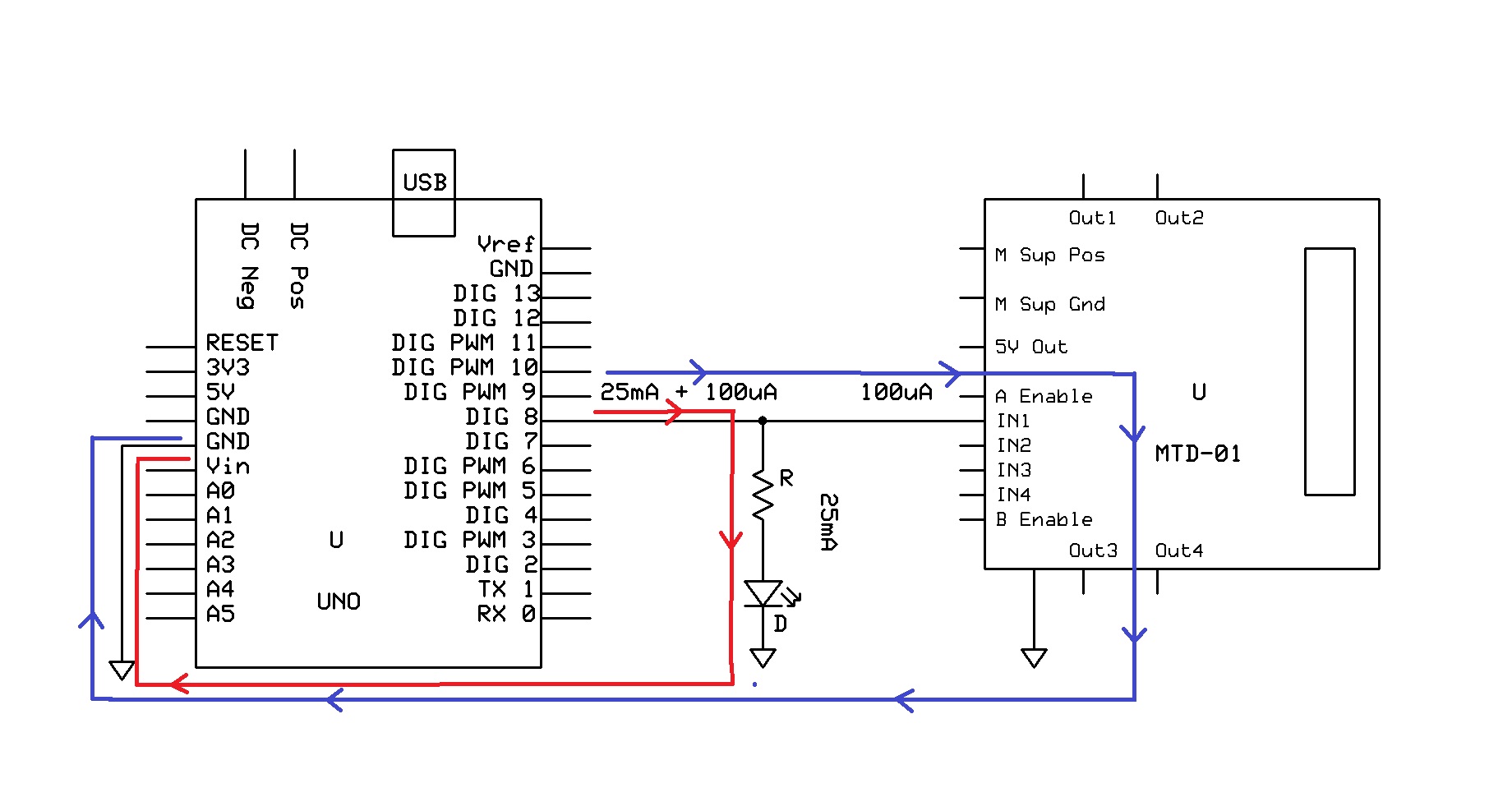
i replace the second LED and draw it like this, right ?
if i probe the GND and PWM-in pin (on the module) - and measure the resistance, i can then figure out how much current is drawn from the Arduino pin at 5 Volts.
i hope i got this right - it can't get any more basic !
TomGeorge:
Current through R1 = V/R1 = (5 - 2)/330 = 0.009A or 9mA
So two LEDS = 2 * 9 = 18mA
yeah, there was actually an earlier picture in the sequence and i got lazy in rounding up when captioning that pic.
thanks for pointing it out and keeping it accurate.
TomGeorge:
Hi,
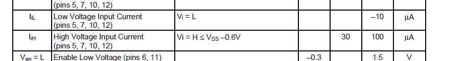
Don't worry about the current going into the control pins of the L298.
What you have there will work, without causing any overload or damage to your controller.
okay - good to know, i can be a bit more at ease.
TomGeorge:
The input pin current load of the L298 is maxium 100uA, not worth worrying about.
didn't want to rely too much on the actual specs because the module i got is a cheap knock-off (less than a dollar more than just the L298N chip itself !)
infact, i think the chip on the module is somewhat 'busted'; on one of the channels, the reverse polarity won't work! (you get what you pay for )
while i'm just learning to use and control H-Bridges, i guess i can live with it - at least i can make a 2-wheel-drive vehicle go forwards and stop ! (and spin 180^ if it needs to "reverse".)
eventually, i will try to rig up my own H-Bridge with actual MOSFETs and capacitors and flyback diodes.
i just realized i could actually just measure the current while the setup is running !!
(just to be safe and know for sure what that module is 'doing'.)
But in general, you cannot measure that input resistance by just using a DMM on ground. There is not an Ohmic resistor in there.
The easiest way would be to put a resistor in the path (e.g. the minimal value to limit the current to the allowed range, so 250Ohm) and measure the voltage drop over the resistor. Usually, inputs will be very high impedance, so virtually no voltage will drop over the resistor. If you really expect actual current through the input, you might have to probe the voltage with an oscilloscope to capture fast changes.
ElCaron:
But in general, you cannot measure that input resistance by just using a DMM on ground. There is not an Ohmic resistor in there.
i see, yeah - i guess there's a whole of circuitry (not just "resistance") going on between that GND pin and the PWM-in pin that one can't just measure it like a resistor; not "Ohmic" as you say).
ElCaron:
The easiest way would be to put a resistor in the path (e.g. the minimal value to limit the current to the allowed range, so 250Ohm) and measure the voltage drop over the resistor. Usually, inputs will be very high impedance, so virtually no voltage will drop over the resistor. If you really expect actual current through the input, you might have to probe the voltage with an oscilloscope to capture fast changes.
what i did do is measure the current with the multimeter (not yet DMM, still too n00bie to invest in a good DMM...)
the needle (!!) didn't budge at all - being in the micro-Amperes level i suppose it was to be expected.
i did try measuring it through the LED and that certainly moved the needle - PWM value of 200 showed 20mA and max-ing out at PWM=255 drew 25mA current for the LED.
so now i'm wondering - the Arduino is confirmed safe, but if the PWM line to the module is also sharing up to 25mA going to LED (in parallel) - that would ruin the PWM-input on the module side, right ?
Your multimeter alsi just measures voltage over a known resistor in serial. The difference to my suggestion is that it is too small to protect the Arduino (or if you are unlucky even itself).
ElCaron:
Your multimeter alsi just measures voltage over a known resistor in serial. The difference to my suggestion is that it is too small to protect the Arduino (or if you are unlucky even itself).
sorry, i didn't quite understand - what is "too small" to protect the Arduino ?
and was my understanding correct that the PWM-line in parallel with an LED could end up passing 25mA current as well ?
BabyGeezer:
sorry, i didn't quite understand - what is "too small" to protect the Arduino ?
If you use a 250Ohm resistor in series and only 5V are involved, then the pin will never exceed the 20mA rating. If you instead use the very small resistor used in your multimeter for measuring current, a low impedance input (e.g. from a current driven amp) could damage your Arduino.
BabyGeezer:
and was my understanding correct that the PWM-line in parallel with an LED could end up passing 25mA current as well ?
I don't understand that, but it sounds wrong. Also note that during the duty cycles of the PWM signal, there will always be a current of 25mA, your slow multimeter just averages it out.
ElCaron:
If you use a 250Ohm resistor in series and only 5V are involved, then the pin will never exceed the 20mA rating. If you instead use the very small resistor used in your multimeter for measuring current, a low impedance input (e.g. from a current driven amp) could damage your Arduino.
oh, i see - protection for the Arduino when measuring current (especially for potentially large currents (ie. "low impedance input").
and relatedly, if i am concerned for the (over)current to the PWM-pin (out from Arduino, in to module) then i can just add a current limiting resistor.
ElCaron:
I don't understand that, but it sounds wrong. Also note that during the duty cycles of the PWM signal, there will always be a current of 25mA, your slow multimeter just averages it out.
i was comparing it to the two LED circuit where the current becomes more when adding a parallel line, does this NOT apply in the case of the motor module because it is a high impedance input ?
but even when the PWM was at 100% duty cycle, i didn't measure a noticeable current through the Arduino pin to the PWM-pin on the module - being that the module only draws 100uA max.
i was comparing it to the two LED circuit where the current becomes more when adding a parallel line, does this NOT apply in the case of the motor module because it is a high impedance input ?
No, the LED part gets the current it gets, plus 100µA from the input. Kirchhoff's law of current.
Or, differently phrased: 100µA means 50kOhm. What is 50kOhm in parallel with 330Ohm? The formula is 1/R = 1/R1 + 1/R2.
but even when the PWM was at 100% duty cycle, i didn't measure a noticeable current through the Arduino pin to the PWM-pin on the module - being that the module only draws 100uA max.
Yes, but you also have an led. What I am telling you is: If you measure 25mA at full duty cycle, there will also be periods of 25mA at lower duty cycles, despite the fact that you are not measuring them with your slow multimeter. So you cannot say "I am only running this at up 80% duty cycle, to it is fine." You are still exceeding the recommended 20mA for a good part of time. Depending on the PWM frequency is is more or less of a problem.
ElCaron:
No, the LED part gets the current it gets, plus 100µA from the input. Kirchhoff's law of current.
Or, differently phrased: 100µA means 50kOhm. What is 50kOhm in parallel with 330Ohm? The formula is 1/R = 1/R1 + 1/R2.
hmm, i guess i never really understood electric flow properly beyond Ohm's law - i was of the understanding that in a closed circuit loop, the current is the same at all points - which is why i kept thinking what the LED gets, the module PWM input also gets.
so; in Tom George's schematic (Thanks so much btw, it certainly helps more than my silly pictures in trying to identify what is happening and where.) - i was thinking that the blue line and the red line have the same current - what would you call this circuit where there are differing currents flowing ?
btw, that 50kOhm is what you would call the impedance of the module, right ?
i need to know when to calculate R (or impedance (Z) ) from V/I (the 100uA case) and when to use I = V/R.
i kept thinking that current (I) was given (throughout the circuit), hence the thinking of what LED gets, module also gets.
TomGeorge:
Hi,
You do not have to worry about the impedance of the input to the motor driver, the current into it is insignificant.
An extra 100uA will not cause an overload of the controller.
yes, i wasn't worried anymore about the Arduino, but when i was thinking of "same current everywhere", that got me to worrying about the motor module, instead of 100uA it was (i thought potentially) going to get 25mA - because of the parallel line and that "current is the same everywhere in a closed circuit loop".