Hi,
We´re currently using a Three Channel Optical Incremental Encoder Module with Codewheel. We have tried to connect it via a breadboard to Arduino and use it to count rotations of the code wheel with the code posted below.
Our question is, how do you connect the circuit on page 5 of the datasheet found here (http://www.farnell.com/datasheets/20523.pdf?_ga=2.95589916.1495636436.1494940026-503011752.1494940026) using a breadboard?
Also, when we connect it up as we think it should be (without connecting I channel) the serial monitor counts to around 14 and stops.
When just connecting a resistor across the A channel which goes to pin 3, the serial monitor counts down from 65 thousand and something (max counts).
In each case, rotating the code wheel does not have any effect, the serial monitor continues as described above.
Any help would be greatly appriciated.
Cheers!
code:
/* read a rotary encoder with interrupts
  Encoder hooked up with common to GROUND,
  encoder0PinA to pin 2, encoder0PinB to pin 4 (or pin 3 see below)
  it doesn't matter which encoder pin you use for A or B

  uses Arduino pull-ups on A & B channel outputs
  turning on the pull-ups saves having to hook up resistors
  to the A & B channel outputs

*/
// If the encoder shaft is attached to a wheel, you can calculate linear distance that the wheel rolls from the counts.
//distance = (wheel circumference)*counts/(counts per complete revolution)

//For accurate results use float variables.
#define encoder0PinA  3
#define encoder0PinB  4

volatile unsigned int encoder0Pos = 0;

void setup() {


 pinMode(encoder0PinA, INPUT);
 digitalWrite(encoder0PinA, HIGH);       // turn on pull-up resistor
 pinMode(encoder0PinB, INPUT);
 digitalWrite(encoder0PinB, HIGH);       // turn on pull-up resistor

 attachInterrupt(0, doEncoder, CHANGE);  // encoder pin on interrupt 0 - pin 2
 Serial.begin (9600);
 Serial.println("start");                // a personal quirk

}

void loop(){
// do some stuff here - the joy of interrupts is that they take care of themselves
}

void doEncoder() {
 /* If pinA and pinB are both high or both low, it is spinning
  * forward. If they're different, it's going backward.
  *
  * For more information on speeding up this process, see
  * [Reference/PortManipulation], specifically the PIND register.
  */
 if (digitalRead(encoder0PinA) == digitalRead(encoder0PinB)) {
   encoder0Pos++;
 } else {
   encoder0Pos--;
 }

 Serial.println (encoder0Pos, DEC);
}

/* See this expanded function to get a better understanding of the
* meanings of the four possible (pinA, pinB) value pairs:
*/
void doEncoder_Expanded(){
 if (digitalRead(encoder0PinA) == HIGH) {   // found a low-to-high on channel A
   if (digitalRead(encoder0PinB) == LOW) {  // check channel B to see which way
                                            // encoder is turning
     encoder0Pos = encoder0Pos - 1;         // CCW
   }
   else {
     encoder0Pos = encoder0Pos + 1;         // CW
   }
 }
 else                                        // found a high-to-low on channel A
 {
   if (digitalRead(encoder0PinB) == LOW) {   // check channel B to see which way
                                             // encoder is turning
     encoder0Pos = encoder0Pos + 1;          // CW
   }
   else {
     encoder0Pos = encoder0Pos - 1;          // CCW
   }

 } // NEED THIS VALUE TO THEN USE FOR DRIVING BACK THE OTHER WAY.
 Serial.println (encoder0Pos, DEC);          // debug - remember to comment out
                                             // before final program run
 // you don't want serial slowing down your program if not needed
}

/*  to read the other two transitions - just use another attachInterrupt()
in the setup and duplicate the doEncoder function into say,
doEncoderA and doEncoderB.
You also need to move the other encoder wire over to pin 3 (interrupt 1).
*/
The only functioning code is the interrupt routine which has serial.println. Why are you tying up the program doing this? Why does the main loop do nothing?
Are you also powering the LEDs in the encoder?
Paul
Welcome to the forum. Please read the posting instructions, and modify your original post to place the code within the code brackets.
http://forum.arduino.cc/index.php/topic,148850.0.html
#define encoder0PinA  3
#define encoder0PinB  4
 attachInterrupt(0, doEncoder, CHANGE); // encoder pin on interrupt 0 - pin 2
It does not appear that you are using pin2 for A or B.
Hi cattledog, Thanks for the advice, I've changed the code to correct it now. I didn't spot that, I am new to encoders so thought it would be best to use the Arduino codes from the playground to try and read the encoder. I will correct all pin numbers and get back with the results.
Hi Paul, I'm looking to keep the loop open to eventually drive a DC motor until a certain value of the encoder is reached. I was waiting until I could read the encoder to then write this part. I've connected the encoder to the arduino using the schematic on page 5 of the Farnell datasheet, which should power the LEDs. Should I move the print to the loop?
fiyulut:
Hi Paul, I'm looking to keep the loop open to eventually drive a DC motor until a certain value of the encoder is reached. I was waiting until I could read the encoder to then write this part. I've connected the encoder to the arduino using the schematic on page 5 of the Farnell datasheet, which should power the LEDs. Should I move the print to the loop?
Absolutely! The interrupt code is fine for counting or decrementing. Before accessing the count in the main loop, disable the interrupt, move the count to a work integer, then reenable the interrupt so it can continue counting. Then print the work integer. Look at the "interrupt" help in the IDE.
Paul
Should I move the print to the loop?
Yes.
And, because it is a multibyte variable, you need to make a "protected" copy of the variable so that it can not change while being read. See Nick Gammon excellent interrupt tutorial Gammon Forum : Electronics : Microprocessors : Interrupts
You may want to manage the Serial print of the value by only printing if the value has changed, or place the printouts on a fixed interval with a "blink without delay" millis() timer.
#define encoder0PinA  2
#define encoder0PinB  4

volatile unsigned int encoder0Pos = 0;
unsigned int copy_encoder0Pos = 0;

unsigned long lastDisplayTime;
unsigned long displayInterval = 1000; //one second updates

void setup() {
  pinMode(encoder0PinA, INPUT);
  digitalWrite(encoder0PinA, HIGH);       // turn on pull-up resistor
  pinMode(encoder0PinB, INPUT);
  digitalWrite(encoder0PinB, HIGH);       // turn on pull-up resistor

  attachInterrupt(0, doEncoder, CHANGE);  // encoder pin on interrupt 0 - pin 2
  Serial.begin (9600);
  Serial.println("start");                // a personal quirk

}

void loop() {

  if (millis() - lastDisplayTime >= displayInterval)
  {
    lastDisplayTime += displayInterval;
    noInterrupts();
    copy_encoder0Pos = encoder0Pos;
    interrupts();
    Serial.println (copy_encoder0Pos, DEC);
  }
}

void doEncoder() {

  if (digitalRead(encoder0PinA) == digitalRead(encoder0PinB)) {
    encoder0Pos++;
  }
  else {
    encoder0Pos--;
  }
}
Hi guys,
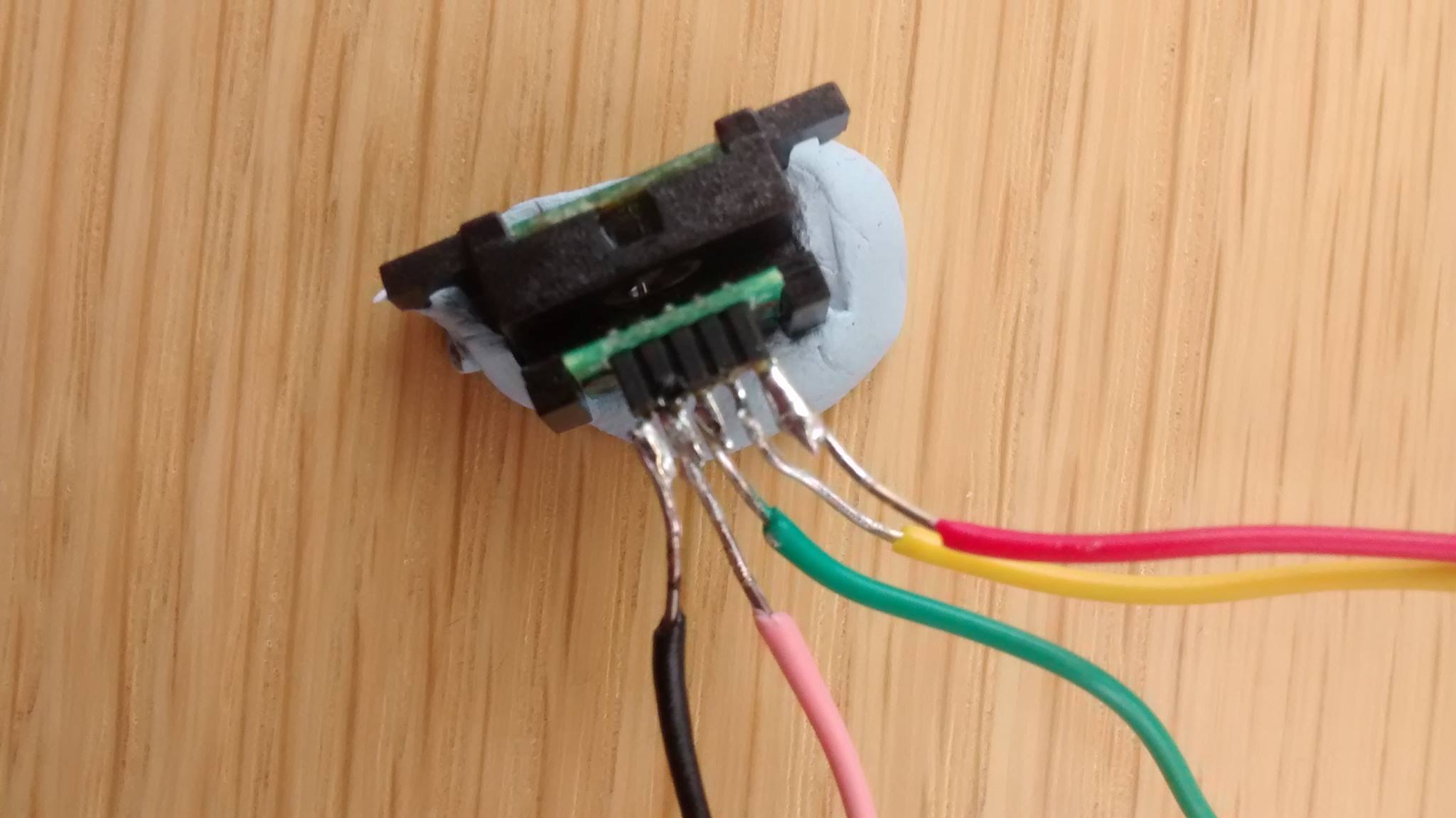
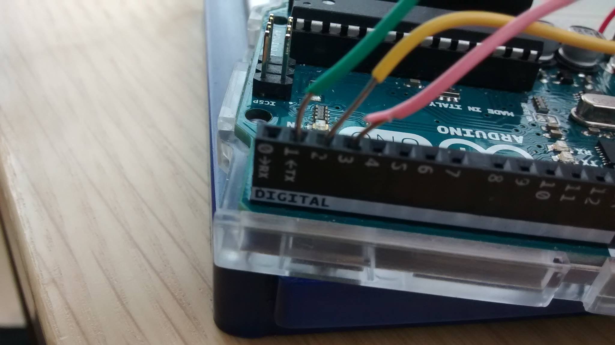
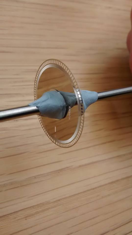
I have tried what was suggested by cattledog, I was unsure what you meant Paul and I'm a bit tight for time so I went for what seemed like the simpler suggestion. See the code below, I managed to get a repeat reading of 0, but no luck within anything other than that. I also tried a few different codes from the playground but no luck. I believe this is because my encoder has an A,B and I pin, as well as a Vcc and GND pin. Please see the connection pictures posted, I believe it is all connected correctly? I'm now very lost as to why I do not get a response from the encoder. Any more help would be great cheers!
#define encoder0PinA  2
#define encoder0PinB  3

volatile unsigned int encoder0Pos = 0;
unsigned int copy_encoder0Pos = 0;

unsigned long lastDisplayTime;
unsigned long displayInterval = 1000; // One second serial updates

void setup() {


  pinMode(encoder0PinA, INPUT);
  pinMode(encoder0PinB, INPUT);


  attachInterrupt(0, doEncoder, CHANGE);  // encoder pin on interrupt 0 - pin 2
  Serial.begin (9600);
  Serial.println("start");                // a personal quirk

}

void loop(){

  if (millis() - lastDisplayTime >= displayInterval)
  {
    lastDisplayTime += displayInterval;
    noInterrupts();
    copy_encoder0Pos = encoder0Pos;
    interrupts();
    Serial.println (copy_encoder0Pos, DEC);
  }
}


void doEncoder() {
  /* If pinA and pinB are both high or both low, it is spinning
   * forward. If they're different, it's going backward.
   *
   * For more information on speeding up this process, see
   * [Reference/PortManipulation], specifically the PIND register.
   */
  if (digitalRead(encoder0PinA) == digitalRead(encoder0PinB)) {
    encoder0Pos++;
  } else {
    encoder0Pos--;
  }
}
The code you posted works with my test encoder. There is an issue with the use of unsigned int for the position in that it won't show negative numbers as positions but that is not your major issue for now. I believe that you have some sort of wiring or hardware problem.
You should perform a simple test with digitalRead() of the A and B pins, when you block the encoder slot completely and then let it be open. You should see verify that they give 1's and 0's. If there is unchanging output, then something is wrong with the wiring.
If you indeed see changing output when open and blocked, are you certain that the code wheel is properly aligned in the encoder?
As a different matter, the green wire should not be connected to pin 1. That is the serial TX pin, and connection to it can create problems with the serial output. But since you are indeed seeing output of 0 on the monitor, that's not the major issue either.
Thanks cattledog,
we managed to get the encoder working correctly thanks for all the help. You were correct it was a wire issue getting enough power to the encoder.