Hi, I am trying to read data from a GPS terminal via serial interface (RS232) using a TnyPico Nano TinyPICO Nano — TinyPICO
Between the Nano and the GPS I have a TTL-RS232 converter Amazon.com
The Nano can send messages which are received correctly and the GPS sends replies back correctly on its TX pin. The voltage of the received signal on the Nano end depends on the supply voltage I give the TTL-RS232 converter, let's say 3.3V. Now when I connect the Nano Rx pin to the TTL rx pin the 3.3V signal gets "cut" and becomes compressed from 3.0V to 3.3V. I can see the shape of these "compressed" signals and the bit sequence correctly with a logic analyzer/oscilloscope, but of course the Nano can't read the data.
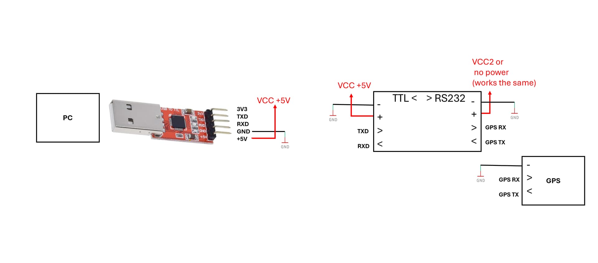
I tried to swap the Nano with any USB to TTL Serial 3.3V chip and I have no problem. It is just the Nano that compresses the signal for some reason. Same issue at different voltages than 3.3V
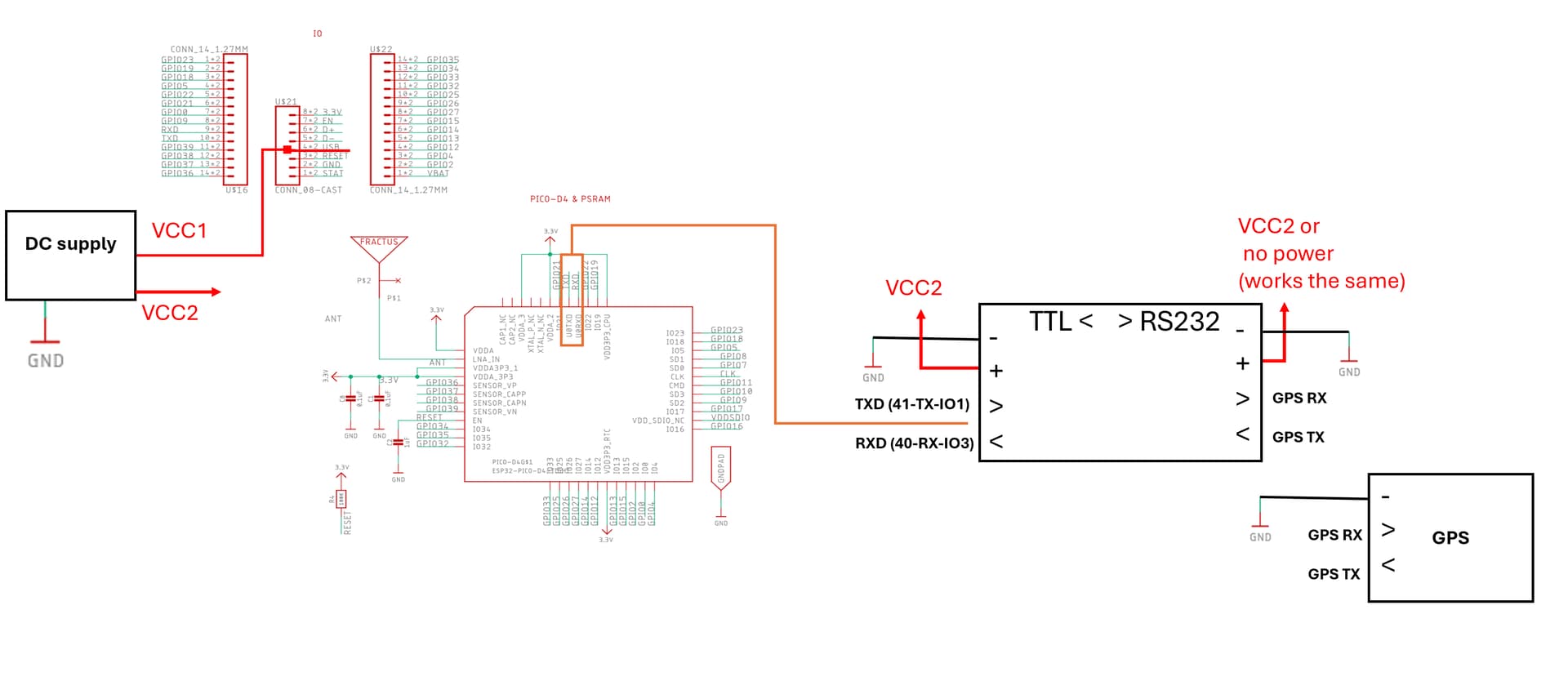
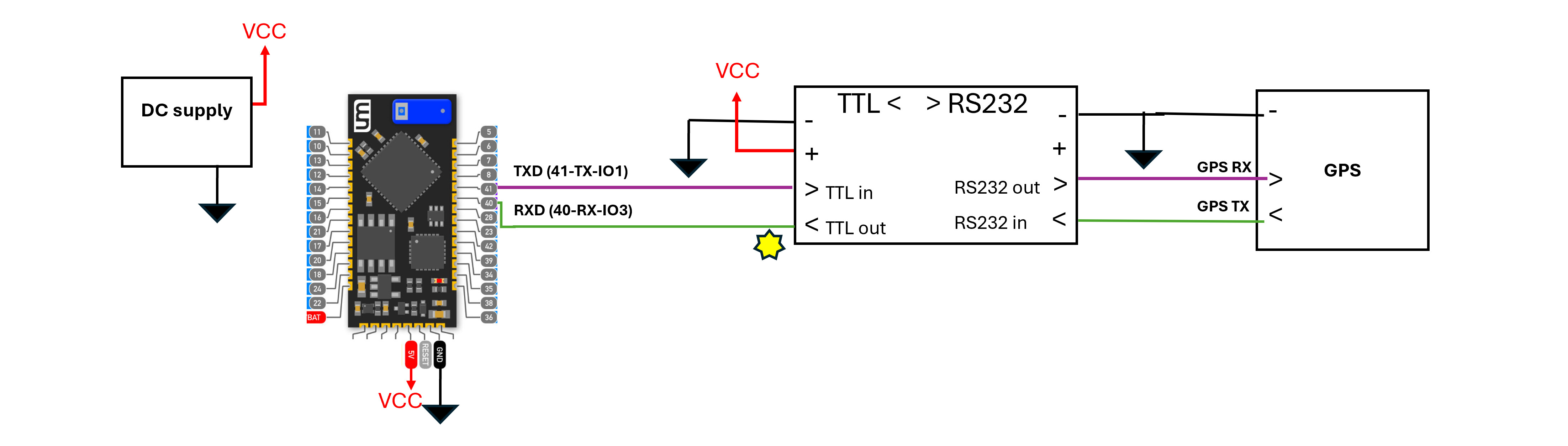
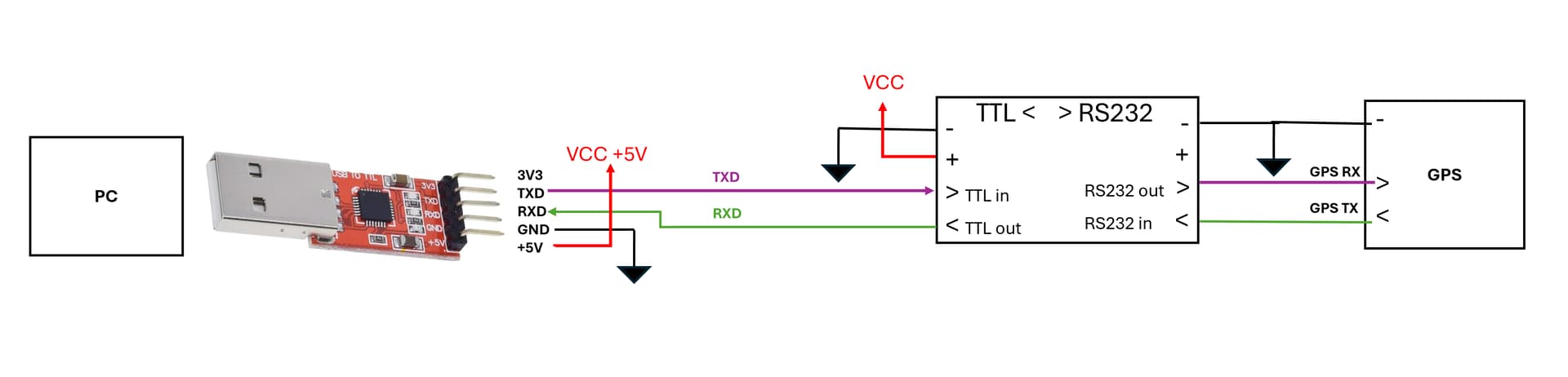
The red-and-green schematics are form Nano web page
41-TX-IO1 is from Nano datasheet, it means: pin 41 of Nano board, TX Uart, Arduino IO pin 1.
I tried different combinations of VCC1 and VCC2, 3.3V-5V.
As for powering the TTL-RS232 converter I didn't see any difference if I power both sides or only one. I was expecting the two sides to take different voltages but they are tied together somehow and both take the highest of the two
The GPS has its own internal battery for supply
I grounded the GPS with the circuit so the signals have the same reference
These are the signals on RXD pin of the TTL-RS232 converter without connecting the RXD pin of the Nano and after connecting it. The data sequence is correct
We have this and that, please post an annotated schematic showing exactly how you have wired it with pin names and numbers. Be sure to show all components, grounds, power and power sources.
Transistor-transistor logic (TTL) voltage levels are 0–0.8 V for a "low" signal and 2–5 V for a "high" signal. TTL circuits use these voltage levels to represent logic 0 and 1.
A typical TTL (Transistor-Transistor Logic) Vcc voltage range is between 4.75V and 5.25V; meaning most TTL circuits operate with a nominal power supply voltage of 5V, with a tolerance range of +/- 0.25V.
Have you looked at the data sheet: Pin 17 +3.3V output from integrated LDO regulator. This pin should be decoupled to ground using a 100nF capacitor. The main use of this pin is to provide the internal +3.3V supply to the USB transceiver cell and the internal 1.5kΩ pull up resistor on USBDP. Up to 50mA can be drawn from this pin to power external logic if required. This pin can also be used to supply the VCCIO pin.
Here I was referring to TXD and RXD on the red FT232 USB dongle.
I didn't decouple Pin 17 (3V3) because I am not using it.
It is just the Pico that compresses the signal for some reason. Or, rather than the Pico I should say the ESP32 chip, because that's the chip I'm communicating with. I tried with a custom PCB where I only have the ESP32 and the issue is the same. It is like the FT232 has something that prevents the issue.
I also used a different RS232 adapter, didn't solve the issue
The data sheet states this: This pin should be decoupled to ground using a 100nF capacitor. It says nothing about whether you are using the pin or not. That filters the internal 3V3 VCC the chip is using. I recommend reading the data sheet again.
I think that there is a little bit of confusion. I am not using the chip, but the whole FT232RL board with USB connector, it already has the decoupling internally. And this one works. The problem is just the TinyPico In fact I just tested an Arduino Nano 33 IOT and it works perfectly
I might have used the wrong word. By compressed I meant in amplitude, so I probably should have said clipped? The time duration of the signal is correct, the amplitude is affected.
Yes I used an oscilloscope or a digital analyzer in analog mode. Reposting the figures:
Signal on TTL_out pin With RDX-TTL_out disconnected
That looks like a bad ground or output device (transistor or MOSFET) that drives it low has failed. Try taking the signal and put something in the 2K range to ground and see what it looks like. It should not change much. If that is correct then the converter is overloading the pin. Is there anything else connected to it?