That's switch S3 from the larger demonstration schematic in #12 which shows the variety of choices. S3 happens to be the easiest, and is the best for reasons.
Now a pro tip is that adding "Arduino" to any search on google will focus your results.
We can spoon feed this stuff endlessly, but it gets tiresome and sooner later you will find no one willing to stick around doing.
using pushbuttons Arduino
Spend 5 minutes on each of 6 of the hits and you'll prolly learn enough to scrape forward in half an hour.
Can you please post a copy of your circuit, a picture of a hand drawn circuit in jpg, png?
Hand drawn and photographed is perfectly acceptable.
Please include ALL hardware, power supplies, component names and pin labels.
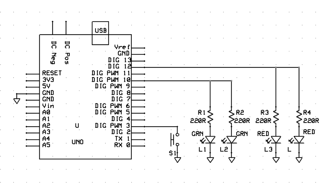
Not exactly the same as previous schematic. Resistor was removed from button, and one of the wires was moved to D3 as shown in switch wiring schematic. If the other wire is incorrectly connected, would appreciate clarification.
One step solved. Now for the code to make it do what I need it to. Which is simply to start with green leds on when Uno is powered up, first button press to switch green off and red on, then red off and green on with next press, and so on. In other words, LEDs selected stay on until next press of button.
Simpler, but not what I am trying to accomplish. There will be two paired green and red LEDs. They will alternately be red on and green off, then red off and green on, controlled by button press to switch between the two states.
You could use a latching SPDT pushbutton and save yourself an Arduino.
I do say if you are going to kill it you might as well overkill it while you are at it, but if all you need is push for green, push for red involving a microprocessor could arguably be way over killing it.
This circuit will be installed in a project that will be triggering the change via an internal part being rotated clockwise for button press, then counterclockwise to press the button again to
switch the lights. I could accomplish this using a NO/NC reed switch and a magnet that would be pushed back and forth to trigger the switch from NO to NC and back again, but not sure
how reliable it would be. I also have a mini Uno board that I found online that takes up less space than a Nano board, so space isn't an issue, but rather reliability versus a mechanical alternative.
Hereby a hardware approch, feel free to experiment with it.
None of the resistance values matter, nor does the wattage.
For the 470 ohms use 1/2watt and for the 22o ohms use 1/4 watt.
If you planed to do it the chinees way, you can even reduce the number of resistors.