Looks good; what kind of microswitch would be needed for circuit?
A single pole changeover switch will do the job.
The dimensions depend on your mechanical construction.
I meant physically, what type. There is a rotating disk that will have a tab or nub on the edge that will trigger the switch, A sliding switch won't work, as there isn't any way to reverse the position via contact, and it is too stiff to be moved bu opposing magnets (already tried that).
Two leds in parallel from one digital output with 220 ohm resistors is pushing the limit.
I recommend 560 ohm resistors.
Did you look at the examples to the Button Library?
Tom... ![]()
![]()
![]()
![]()
It seems there is a mechanical issue no matter what you do with the contacts opening and closing to make electricity flow.
I'm not so mechanically inclined, so I can't visualize this aspect of the project. What makes the rotation stop and reverse at the point where somehow a single button is also pressed to turn red off and green on and vice all versas at the opposite end of the rotation?
Could it be easier with two switches similar to limit switches seen in linear movements?
This would have the advantage (!) of being more reasonably handled by an Arduino… I don't think I am alone in have aimed that kind of blowtorch at what is essentially butter.
Another consideration is that once an Arduino is part of the project, it might be possible for it to pick up other things and do them differently, or for adding features you wouldn't have dared to even dream of.
a7
I did. There is only one example. It is for turning on and off one LED. Expanding it to include two pairs of LEDs, switching between them with each button press is something I have tried over the years to master (adding functions to existing sketches) and failed. I have been able to make simple adjustments, but that is as far as I have been able to get. Maybe I'm stupid, but I can't wrap my brain around any kind of programming from scratch.
So what's the order of operations? At powerup what state must the LEDs be in? Does it matter? In the end what is the function of the device?
Starting to read like an X-Y problem.
Hi, @tuslcd497
Post that example please.
Thanks.. Tom... ![]()
![]()
![]()
![]()
PS. I'm currently at work, but others should be able to mod it for you.
/*
  Button

  Turns on and off a light emitting diode(LED) connected to digital pin 13,
  when pressing a pushbutton attached to pin 2.

  The circuit:
  - LED attached from pin 13 to ground through 220 ohm resistor
  - pushbutton attached to pin 2 from +5V
  - 10K resistor attached to pin 2 from ground

  - Note: on most Arduinos there is already an LED on the board
    attached to pin 13.

  created 2005
  by DojoDave <http://www.0j0.org>
  modified 30 Aug 2011
  by Tom Igoe

  This example code is in the public domain.

  https://www.arduino.cc/en/Tutorial/BuiltInExamples/Button
*/

// constants won't change. They're used here to set pin numbers:
const int buttonPin = 2;     // the number of the pushbutton pin
const int ledPin =  13;      // the number of the LED pin

// variables will change:
int buttonState = 0;         // variable for reading the pushbutton status

void setup() {
  // initialize the LED pin as an output:
  pinMode(ledPin, OUTPUT);
  // initialize the pushbutton pin as an input:
  pinMode(buttonPin, INPUT);
}

void loop() {
  // read the state of the pushbutton value:
  buttonState = digitalRead(buttonPin);

  // check if the pushbutton is pressed. If it is, the buttonState is HIGH:
  if (buttonState == HIGH) {
    // turn LED on:
    digitalWrite(ledPin, HIGH);
  } else {
    // turn LED off:
    digitalWrite(ledPin, LOW);
  }
}
The switch doesn't know direction, only actuation?
Hi, @tuslcd497
Try this code;
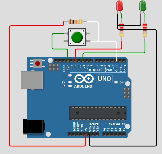
const int greenLedPin = 12; // Green LED connected to pin 12
const int redLedPin = 10;   // Red LED connected to pin 10
const int buttonPin = 2;    // Momentary button connected to pin 2

bool isGreenOn = true;      // Tracks which LED is currently on
bool buttonState = false;   // Current state of the button
bool lastButtonState = false; // Last recorded state of the button

void setup() {
  pinMode(greenLedPin, OUTPUT);  // Set green LED pin as output
  pinMode(redLedPin, OUTPUT);    // Set red LED pin as output
  pinMode(buttonPin, INPUT);     // Set button pin as input

  // Start with green LED on
  digitalWrite(greenLedPin, HIGH);
  digitalWrite(redLedPin, LOW);
}

void loop() {
  buttonState = digitalRead(buttonPin); // Read the button state

  // Check for a button press (change from LOW to HIGH)
  if (buttonState == HIGH && lastButtonState == LOW) {
    // Toggle the LED state
    if (isGreenOn == true) {
      isGreenOn = false;
    } else {
      isGreenOn = true;
    }

    // Update LED states
    if (isGreenOn == true) {
      digitalWrite(greenLedPin, HIGH);
      digitalWrite(redLedPin, LOW);
    } else {
      digitalWrite(greenLedPin, LOW);
      digitalWrite(redLedPin, HIGH);
    }

    // Debounce delay
    delay(50);
  }

  // Update the last button state
  lastButtonState = buttonState;
}
Note the button connection.
This doesn't use the Button library, but it works.
Tom.. ![]()
![]()
![]()
![]()
![]()
![]()
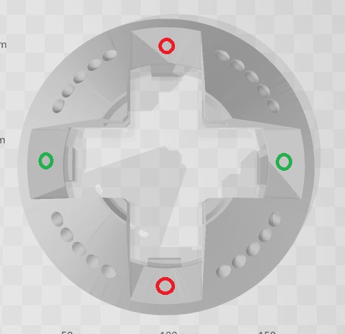
Correct. There is a handle attached to a shaft that fits in the middle of the part. On the bottom edge of the shaft, there is a flange that will have a tab that will press the button
when the handle and shaft is rotated a quarter turn. There is also vertical movement of the handle and shaft, which is why the change of lights needs to happen before the cycle is completed.
Handle and shaft is raised, rotated a quarter turn (which is when the button is pressed), then lowered. This is to turn on all the other lights and chaser circuit (for the round cutouts on the side of the top piece) which will be done using leaf switches, which would be pressed by the same flange at the bottom of the shaft when the handle and shaft were in their fully lowered position. Lifting up the handle and shaft would turn off all the items controlled by the leaf switches, leaving the top LEDs to be separately controlled. There is much more to the project than the top piece shown.
Looks really good. Just need to add one more red and green LED, so there are pairs of each color. Picture attached shows part they will be located in. Both green will be on when Uno is powered on. Button press will switch to the two red LEDs, turning off the green. Second button press will turn off red LEDs and turn back on green LEDs. There is a longer description in my recent post explaining how the process will be done.
No, it doesn't, not if the switch bounces.
And since the button is pulled up, this
// Check for a button press (change from LOW to HIGH)
is exactly wrong. But thta makes no difference, it would, if the sketch worked, only meant the action would take place on releasing rather than pressing.
The poor man's debounce delay is not in the correct place.
    // Debounce delay
//    delay(50);
  }

delay(50);

  // Update the last button state
  lastButtonState = buttonState;
}
I did not catch it failing, but it remains somewhat suspect, as the if statement is not looking for any state change, rather just the one edge. This might mean it could catch bouncing on that edge; I am not sure of this and analysis is more taxing than simply using the common programming pattern that
- looks for any transition
- reacts when said transition is the edge (going pressed or going released)
and only doing that at a rate that is very slower than any bouncing.
This was revealed in posts #15 and #17 above.
a7
Hi,
Instead of two red leds in parallel, put the two leds in series and lower the series resistor value.
Likewise with the green.
More efficient and lower current draw on the Arduino output.
Tom.. ![]()
![]()
![]()
![]()
Just finished building the circuit in Wokwi, and typed all the lines of code in manually, since I couldn't simply copy and paste it. After several typo corrections, the code compiled correctly, but the circuit doesn't work. Green Led isn't on when simulation starts, and nothing happens with button press. I used the resistor values according to the color bands, but not sure if that is the problem.

Also tried the serial connection for the LEDs; still doesn't work.
SUCCESS!!! I tried the serial connection for the LEDs, didn't work. Tried my original parallel connection, AND IT WORKS! However, the colors were reversed. It started with the red LEDs on, then switched to the green LEDs when the button was pressed, then back to red on next press. I had to switch the pin assignments in the code to get the correct color sequence. So now I have working circuit and code. Thank you so very much!

