You should be able to copy and paste.
If you place the cursor where the white arrow a "copy" icon appears.
Tom.. ![]()
![]()
![]()
![]()
You should be able to copy and paste.
If you place the cursor where the white arrow a "copy" icon appears.
Tom.. ![]()
![]()
![]()
![]()
I wasn't signed in to the site, so I wasn't able to paste the code you provided into the app. At least it gave me some time to look at the code and try to figure out how it works.
Hi,
Good to see it working.
It seems Wowki doesn't like LEDs in series.
Fine on the LED colours, it was a quick write during lunch at work.
Good luck.. Tom.. ![]()
![]()
![]()
![]()
It turns out you were right about the LED hookup. Finally got the circuit to work the way I needed it to.
Nice. Thanks for telling.
Please post links to any wokwi simulation, especially ones you say anything at all about. And def any that you claim are the solution to the problem.
I do not know why you couldn't paste your code into someone else's wokwi. I am doing it alla time on a machine that has no idea I am a wokwi supporter and could sign in if I wanted to.
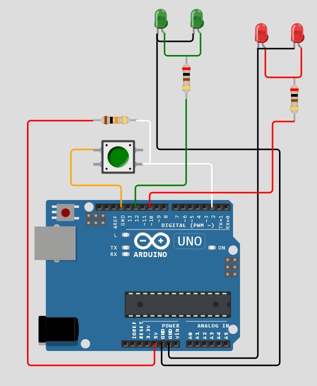
Your diagram shows one resistor serving two LEDs. Each LED needs its own series current limiting resistor; in the wokwi it matters not, the LEDs are magical in the sense that they need no current limiting and are basically indestructable anyway.
Interesting. wokwi does not pretend to very good analog simulation - just enough to get by but this surprises me.
a7
When I said in #56 that the code in #53 does not work, I meant by that to say that the code in #53 does not work.
Here it is in the simulator. Pressing the button does not reliably turn on and off the LED, which I believe is the desired functionality.
Selecting the pushbutton in the diagram window and turning off its simulated bouncing results in a sketch that does turn on and off the LED. This points a finger at the button handling.
Anyone finding the sketch to function correctly must have magic fingers that are pressing the button just so; this will not obtain in real life either with cam shafts or other ppl doing the pressing.
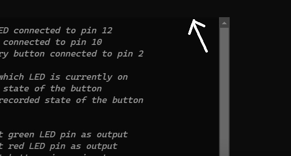
Cut from #53 and pasted into the wokwi sketch window,
// https://wokwi.com/projects/419934249552519169

const int greenLedPin = 12; // Green LED connected to pin 12
const int redLedPin = 10;   // Red LED connected to pin 10
const int buttonPin = 2;    // Momentary button connected to pin 2

bool isGreenOn = true;      // Tracks which LED is currently on
bool buttonState = false;   // Current state of the button
bool lastButtonState = false; // Last recorded state of the button

void setup() {
  pinMode(greenLedPin, OUTPUT);  // Set green LED pin as output
  pinMode(redLedPin, OUTPUT);    // Set red LED pin as output
  pinMode(buttonPin, INPUT);     // Set button pin as input

  // Start with green LED on
  digitalWrite(greenLedPin, HIGH);
  digitalWrite(redLedPin, LOW);
}

void loop() {
  buttonState = digitalRead(buttonPin); // Read the button state

  // Check for a button press (change from LOW to HIGH)
  if (buttonState == HIGH && lastButtonState == LOW) {
    // Toggle the LED state
    if (isGreenOn == true) {
      isGreenOn = false;
    } else {
      isGreenOn = true;
    }

    // Update LED states
    if (isGreenOn == true) {
      digitalWrite(greenLedPin, HIGH);
      digitalWrite(redLedPin, LOW);
    } else {
      digitalWrite(greenLedPin, LOW);
      digitalWrite(redLedPin, HIGH);
    }

    // Debounce delay
    delay(50);
  }

  // Update the last button state
  lastButtonState = buttonState;
}
a7
Those leds are in parallel, not in series.
In parallel, each led should have its own resistor..
It does here;
Tom.. ![]()
![]()
![]()
![]()
You have the bouncing turned off!
That's cheating or missing the point or both.
Click on the pushbutton in the diagram window and check the "Bounce" box; try it again.
a7
Thank you, a 0.1uF capacitor would probably fix that in real life.
I did back in post #35 suggest the use of the Button library, which would do most of his work.
In fact Button2 may be better.
https://docs.arduino.cc/libraries/button2/
Tom... ![]()
![]()
![]()
![]()
Then the code could be simpler.
AVR inputs have hysteresis which is a necessary part of debouncing with just a 0.1 uF capacitor; it is not a general solution for all digital inputs.
And a single cap is inadequate, see
Many designers will go with software as it is easy to do correctly and requires nothing special about the input circuitry and zero extra components.
As for libraries, grabbing a random one can disappoint. I've seen libraries with every kind of flaw and every kind of objection one could raise.
ezButton (small e small z big Button) gets my highest praise "it doesn't suck" and using it carefully for what it is good at, reporting button down events, is in fact easy.
If you're gonna use a library.
a7
Because English is not my native language.
Like the well-known song.
By the English-Belgian singer John Makin, better known by his stage name, Mister John.
An English song from 1998.
Potverdekke, it's great to be a Belgian.
I tried something for an Arduino R3.
Other boards will probably work too.
This is really an overkill solution, but oh well, it's fun and for the hobby.
So the Sketch is in Dutch and divided into a main file and a header file.
The header file contains the class and the enum.
This is done to improve readability.
Please any comments or improvements, feel free to translate it to English and try and use it.
The code is self explanatory.
A regular tactile switch can be used.
One side on pin 4, the other on gnd.
Each push of the button changes the led pairs.
You can use the code as it is, but trying to understand it is really the goal.
Read it a few times and understand it in your own language.
The code ;
/*
 * Author:  Gij Kieken
 * Date:    12/01/2025
 * Purpose: Toggle two pair of Led's
 */

#include "LedController.h"
const int knopPin = 4;  // Knop met interne pull-up
const int groeneLedPin = 5; // Eerste groene led pin
const int rodeLedPin = 6;   // Eerste rode led pin
const int groeneLedPin_2 = 7; // Tweede groene led pin
const int rodeLedPin_2 = 8;   // Tweede rode led pin

// Instantie van de LedController klasse
LedController ledController(groeneLedPin, groeneLedPin_2, rodeLedPin, rodeLedPin_2);

// Variabelen voor debouncing en flankdetectie
bool vorigeKnopIngedrukt = false;
unsigned long vorigeMillis = 0;
const unsigned long debounceDelay = 20; // 20 ms debounce voor druk
const unsigned long releaseDelay = 1;   // 1 ms voor loslaten

void setup() {
  pinMode(knopPin, INPUT_PULLUP);  // Knop pin met interne pull-up weerstand
}

void loop() {
  int knopStatus = digitalRead(knopPin);  // Lees de huidige status van de knop
  unsigned long huidigeMillis = millis();

  // Flankdetectie voor knop indrukken
  if (knopStatus == LOW && vorigeKnopIngedrukt == false && (huidigeMillis - vorigeMillis) > debounceDelay) {
    ledController.toggleStatus();  // Toggle de LEDs bij een knopdruk
    vorigeMillis = huidigeMillis;  // Sla de tijd van de knopdruk op
    vorigeKnopIngedrukt = true;    // Zet de knopstatus naar ingedrukt
  }

  // Flankdetectie voor knop loslaten
  if (knopStatus == HIGH && vorigeKnopIngedrukt == true && (huidigeMillis - vorigeMillis) > releaseDelay) {
    vorigeMillis = huidigeMillis;  // Sla de tijd van het loslaten op
    vorigeKnopIngedrukt = false;   // Zet de knopstatus naar losgelaten
  }
}

The header file;
// Enum voor de LED status
enum LedStatus {
  LED_GROEN,  // Groene LED aan
  LED_ROOD    // Rode LED aan
};

// Klasse voor LED besturing
class LedController {
  private:
    int groeneLedPin;
    int groeneLedPin_2;
    int rodeLedPin;
    int rodeLedPin_2;
    LedStatus huidigeStatus;

  public:
    LedController(int groenePin,int groenePin_2, int rodePin, int rodePin_2) { // Constructor
      groeneLedPin = groenePin;
      groeneLedPin_2 = groenePin_2;
      rodeLedPin = rodePin;
      rodeLedPin_2 = rodePin_2;
      huidigeStatus = LED_GROEN;  // Begin met de groene LED aan
      pinMode(groeneLedPin, OUTPUT);
      pinMode(groeneLedPin_2, OUTPUT);
      pinMode(rodeLedPin, OUTPUT);
      pinMode(rodeLedPin_2, OUTPUT);
      digitalWrite(groeneLedPin, HIGH);    // Zet de groene LED aan bij opstarten
      digitalWrite(groeneLedPin_2, HIGH);  // Zet de tweede groene LED aan bij opstarten
      digitalWrite(rodeLedPin, LOW);       // Zet de rode LED uit
      digitalWrite(rodeLedPin_2, LOW);     // Zet de tweede rode LED uit
    }

    void toggleStatus() {
      if (huidigeStatus == LED_GROEN) {
        setStatus(LED_ROOD);  // Zet de rode LED aan, groene uit
      } else {
        setStatus(LED_GROEN);  // Zet de groene LED aan, rode uit
      }
    }

    void setStatus(LedStatus status) {
      if (status == LED_GROEN) {
        digitalWrite(groeneLedPin, HIGH);
        digitalWrite(groeneLedPin_2, HIGH);
        digitalWrite(rodeLedPin, LOW);
        digitalWrite(rodeLedPin_2, LOW);
      } else if (status == LED_ROOD) {
        digitalWrite(groeneLedPin, LOW);
        digitalWrite(groeneLedPin_2, LOW);
        digitalWrite(rodeLedPin, HIGH);
        digitalWrite(rodeLedPin_2, HIGH);
      }
      huidigeStatus = status;
    }

    LedStatus getStatus() {
      return huidigeStatus;
    }
};
Exactly, but a learning curve.
A lot of hardware and programming effort just to get a couple of lights to flash.. ![]()
![]()
![]()
A lot of basic functions in the code, the only way to learn.
Like you need 64G of Win11 just to run "Solitaire"... ![]()
![]()
![]()
Tom.. ![]()
![]()
![]()
![]()
It does not work.
It does work if you turn off the button bounce simulation... which means your button handling is faulty.
Did you test this? If you tested it and it works, you are using very well-behaved buttons.
Your code, enough circuitry to demonstrate it here:
Added: easily fixed as far as I can see. I leave that as an exercise for whomever. I did not have to come to much of an understanding of the code, so I cannot say it is solid.
a7
Yes, brand new tactile buttons.
Tom... ![]()
![]()
![]()
![]()
I wasn't using someone else's wokwi simulation, I went to the site and input everything manually. I have never used this site prior to this project, so know very little about how it works. I created the simulated circuit per the poster, input the code (not able to paste the code I copied from the poster) and after correcting typos, the simulated circuit didn't work.
A suggestion was made to connect the LED in parallel instead of serial, which I did, and the simulated circuit started to function. Green LEDs were lit when the Uno was powered on, button press turned off green and turned on red LEDs, and repeated for each button press. No flashing, just on continuously until next button press. Don't know about turning on or off Bounce function in app, only that the simulation was working. Haven't tested the actual circuit yet, as I am waiting for some of the parts to be delivered.
Link to Wokwi simulation with two red and green leds.
Something in the code is causing a switch in the pin assignments for the red and green LEDs. The code has green led pin = 12, and red led pin = 10, but I have to switch them on the simulated circuit in order of the green LEDs to be on when the simulation starts.