Hi, I need to track the value of a 500 Ohm potentiometer with a stepper motor.
I start by saying I'm not very good at programming.
I also hope I have centered the correct forum, in which case can you tell me where I can post this question.
Basically I have to follow the resistive value of a potentiometer that moves from 0 to 500 Ohm doing from 0 to 360 degrees and vice versa.
The potentiometer moves slowly, makes one revolution in about 1.3 minutes.
I would like the stepper motor to track the movement of the potentiometer as it changes its value.
I have tried in several ways, but unfortunately with no appreciable results, I cannot.
If any of you are aware of such a project, could you please indicate where I can find it.
If not, it might help me make it happen.
Does the potentiometer rotate back and forth smoothly between 0 and 500 ohms or is it a "continuous rotation potentiometer" that will rotate past 360° to 0° and discontinuously from 500ohms to 0 ohms like a sawtooth?
Does your project differ from Arduino/File/Examples/Stepper/MotorKnob ?
Wow Hah,
thanks Hah, yes it was what I was looking for, too bad I can't find how to download the code and the connection diagram, it tells me that the link sharing has expired.
Many thanks
Hi DaveX,
it seems that it could do for me, but I have to try it first to see if it works, in the week I will do some tests and I will be able to tell you.
The potentiometer is linear it goes from 0 to 500 Ohm it does not rotate continuously it has an end stop in practice it is 340 degrees but I think that the map I can change the degrees to 360.
Many thanks
A stepper motor doesn't have a 'home' position. Is it OK if the two shafts (input and output) move at the same rate starting at whatever position they were at when the power came on?
The first step is to read the position of the potentiometer. How many pins does it have?
Hi alto777,
yes of course, I have tried several programs copied here and there, unfortunately my programming skills are too poor.
Posting what I've tried that doesn't work, that's a lot of stuff.
and I think it's not worth it.
Yes, I saw the video that does what I would like but unfortunately there is no code and I could not find it plus it is also in Chinese or Japanese ...
Many thanks
Hi johnwasser,
the motor has 5 pins and is geared down, 1:64, but I saw that there is an example of the Stepper library that maybe is right for me, now I have to find the system every time I turn it on to know in what position the potentiometer is so as to move or not to move the motor if it is already in that position.
Thank you
Thanks you have all been very kind and thoughtful, it's a great forum with special people.
Thanks again to everyone, if I have difficulty I will definitely post my problem here again
Hi,
I'm sorry but I don't know how to post a new question at all.
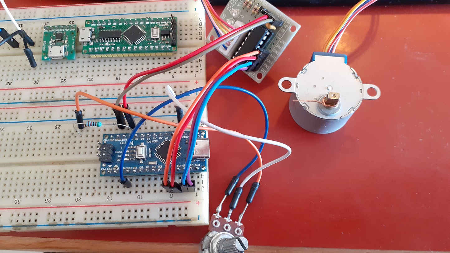
I connected the nano to the ULN2003 and I feed it with the 5V required by the motor.
If I use a potentiometer with 3 pins one to ground, the other to the A0 input and the other to 5V, it seems to work even if it only makes half a turn and not a full turn.
But this is another problem.
The problem is that I have a potentiometer from which I can only take two pins, the central and one on the side, but not the third pin, as shown in the diagram.
In addition I have noticed that the motor does not stay still once it has reached the position but continues to shake as if there were small variations in values.
Any suggestion about ?
#include <Stepper.h>

// change this to the number of steps on your motor
#define STEPS 64

// create an instance of the stepper class, specifying
// the number of steps of the motor and the pins it's
// attached to
Stepper stepper(STEPS, 11, 9, 10, 8);

// the previous reading from the analog input
int previous = 0;
int d ;
void setup() {
  // set the speed of the motor to 30 RPMs
  stepper.setSpeed(500);
   Serial.begin(9600);
 Serial.flush(); // Clear Serial buffer
}

void loop() {
  // get the sensor value
  int val = analogRead(0);
  Serial.println(val);
  d = map(val,0,1005,0,2048);
  // move a number of steps equal to the change in the
  // sensor reading
  stepper.step(val - previous);

  // remember the previous value of the sensor
  previous = val;
}