Hey guys,
I’m very new to electronics, so please excuse my ignorance. I’ve always had an interest in electronics, but always thought it was too confusing for me to understand.
This is going to be a pretty lengthy post, since I’ve made some decent progress on my project already. I’ll give some background on myself, explain some of my experiences, and explain how I plan to go about getting all of this to work in synchronous. I’ve been trying to draw basic designs of what I’m doing in effort to break each part of my project into it’s own step, so I will have some pictures, some screenshots, and some code examples.
Background:
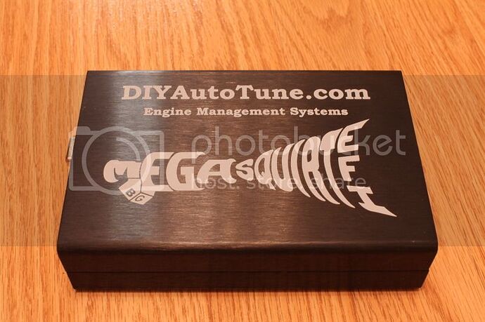
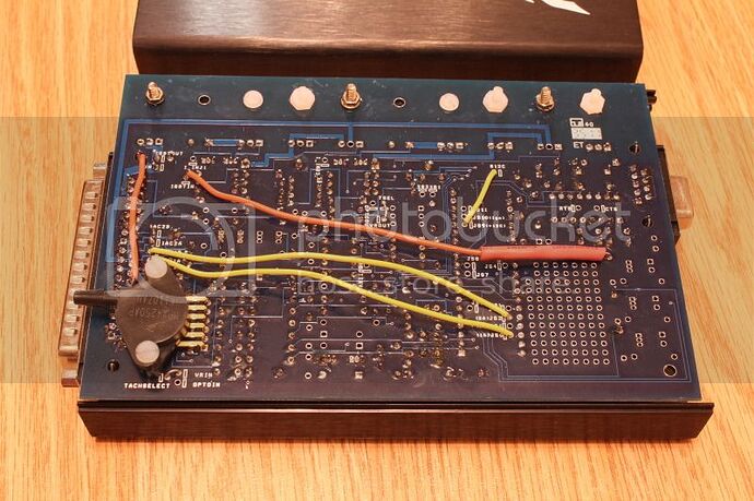
I’m 21 years old. I graduated from a Community College in Des Moines, IA in 2012 with a two-year degree in Computer Programming. I work for a company called Businessolver, which sells an online Benefits Solution. We’re basically the middleman between a large company who supplies benefits to their employees and a vendor of a health service. Our platform is a website, so most of what I do is related to Web Development. I interned for the same company for about a year and a half and am now full time, so I’ve been doing programming (in a professional environment) for just short of two years. I have very little background in electronics. The biggest project I’ve taken on so far was building a MegaSquirt Engine Management System for my car (feel free to check out my build thread, the link is in my signature). Here are a couple pictures of what I built.
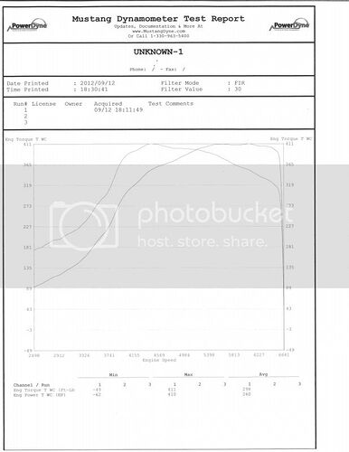
I followed a write-up johnb7 wrote over on CelicaSupra.com. Pretty much all the parts came from diyautotune.com. The car made 410rwhp and 411ftlbs at 20psi.
Though this seems like a pretty good amount of background for someone new to electronics, all I did was follow instructions. I’m very good at completing tasks that are laid out in detailed steps (Though it’s always nice to ask a couple questions here and there. I guess that’s kind of why I’m posting here).
Also, a coworker suggested this book for reading on the basics:
So I went ahead and bought it. I’m about halfway through it now.
Current Project:
Since finishing the MegaSquirt EMS and having everything go phenomenally well, I’ve started to realize the sky is the limit. A friend of mine has a ProEFI (another brand of EMS) which is one of the more expensive (try upwards of $5000 compared to $400) but much more technologically advanced EMS’s on the market. ProEFI has a Traction Control feature. This system uses wheel sensors to determine if the car is losing traction. Once the system determines that the car is losing traction, it limits the engines power; which helps the car regain traction. I kicked around the idea of trying to add this to my MegaSquirt (I did some research and it sounds like people have added it to the MS3 versions; I’m on MS2. Though it sounds like it’s possible). After more research and talking with some friends who have more experience, it started to make sense to have this be independent of the MegaSquirt.
So the general idea is: Detect if the rear wheels are spinning, if they are then limit engine power until they are no longer spinning.
There’s a handful of ways to limit the engine’s power (I’m sure there’s more than I will discuss). 1. Cut Spark, 2. Cut Fuel, 3. Cut Air. We threw around the pros and cons to each one. We decided it would be best to cut air. From what I understand ProEFI cuts either Spark or Fuel. From what I’ve been told (and this could be wrong), if you ran a car down the track without traction control (meaning traction is reliant on the driver pushing the throttle pedal) and then run the same one down the track with traction control (assuming it limits power by either cutting spark or fuel); you will see the one that ran without traction control will run faster passes. This begs the question of, ”Why can’t a computer control the throttle pedal?” With a Drive By Wire (DBW) system, it can. Since the application I will be developing on will be a turbocharged car, I plan to also control boost levels.
Initially the program will grab two inputs: front and rear wheel speed. It will compare front and rear to determine if one is spinning faster than the other. The equation will be something like:
if((((x-y)/y)*100)>z){cutPower();}
Where x is rear wheel speed, y is front wheel speed, and z is the percentage of wheel spin you want to allow. Determining what amount of wheel spin is appropriate will take some trial and error. The cutPower method will do two things: 1. Cut Boost and Cut Throttle. I have a 14psi wastegate spring and the most boost I run right now is 20psi. So this method will first cut a certain amount of boost per loop where wheel spin is greater then z. Once boost is to 14psi, it will start to cut degrees from the throttle (by closing it more and more per loop).
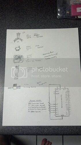
So on to the electronics. Here’s a basic sketch of the inputs.
Here’s the parts list:
Arduino Uno (I may switch to the Micro, since I need more than 6 analog inputs.)
Wheel Sensors (a friend suggest using a Hall type?)
http://www.cherrycorp.com/english/sensors/Speed_Direction/gs101205.htm
Boost Solenoid (This appears to be +12v and ground and uses PWM)
PWM Kit (For the Boost Solenoid. This has the transistor and other need parts)
Map Sensor (This is the same on that’s in my EMS)
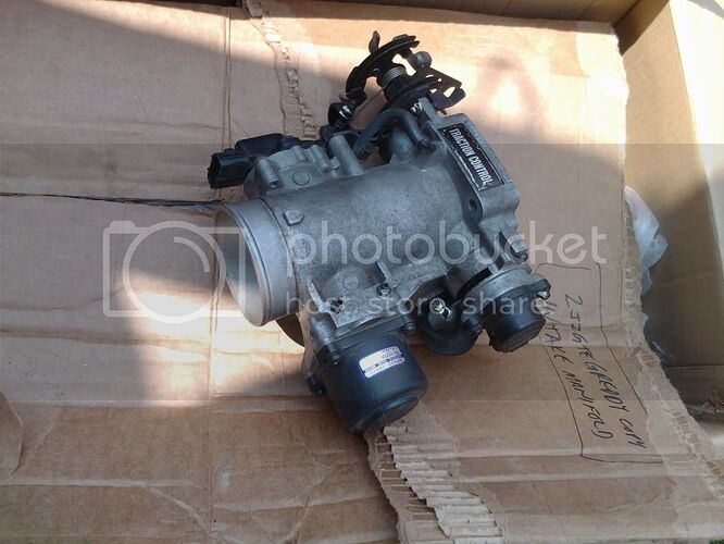
Mazda RX8 DBW Throttle body (Nearly the exact same dimensions as my throttle body)
Mazda RX8 Throttle Pedal (Going to have to find a way to mount this)
Toggle Switches (One for throttle control on/off, one for boost control on/off, one
for my linelock which will disabled bot throttle control and boost control)
Single Din Pocket (Planning to use this as the project enclosure)
(I had to break this post into two posts, because of the length)
