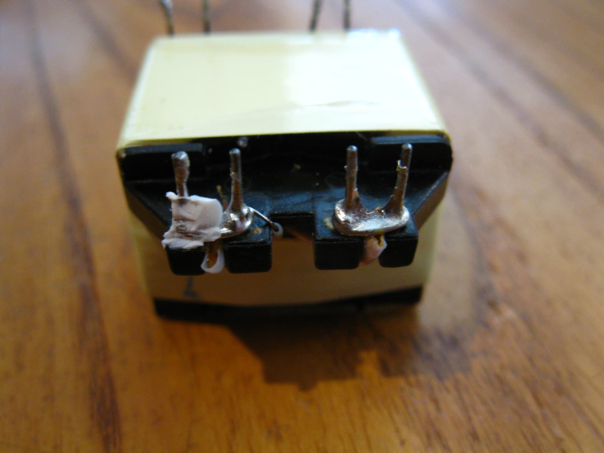
I have desoldered this transformer from an old power supply plugpack, but googling the numbers on it does not return anything.
Does anyone know how to identify what kind of transformer this is?


Well, the case of the plug pack (aka wall wart or tabletop supply, depending on size) would have given you a darn good idea, no? Probably said something like "115VAC in, 9VAC out", unless it had a rectifier, with or without filter capacitor, in which case it probably said something like "12VDC out". If you have a meter, and are careful, you can measure the output with 115 VAC applied to the input, but make sure your room mate has EMS on speed dial, just in case you mess up.
@camsysca
It said 240VAC in, 12VDC out.
But where do I find a datasheet for it?
I'd like to look at a few details of this transformer without buying heaps of special equipment.
Wiser words were never spoken. I've gotten a electric shock before, it's certainly not fun!!
It certainly looks like a high frequency transformer. Undoubtedly a special made for that converter design. If you pull some of the tape off you should see the "core" is made of a ferrite material.
It makes a good paperweight but functionally useless.
Why is that? Can I not use it to drop 240 vac to 12vdc with the appropriate circuit?
In theory however unless you could measure the parameters of the transformer you could not design the appropriate circuit.
1 Like
Or find a datasheet?
As I said:
Undoubtedly a special made for that converter design
2 Likes
So this plugpack had a couple of transistors and ICs in it? And was quite lightweight?
If so, it was a switchmode supply and the transformer operates at a frequency well above the audio range. It does not operate at 50 Hz. ![]()
@Paul_B
It had no IC's, one transistor, three inductors, lots of smd capacitors and resistors, a fuse, 3 electrolytic capacitors and some as yet unidentified componants. It was not switchmode, but fixed voltage. It worked beautifully on our 50hz solar system.
Hi,
Switchmode power supplies are primarily fixed output, its their efficiency that makes them desirable, and wall plug applications are well suited as SMPS than 50/60Hz transformer and linear regulator types.
Can you please post some images of both sides of the PCB, no matter how distressed it is.
These are the sorts of situations you can learn quite a lot, because you don't have to put it back together and make it work. ![]()
Tom... ![]()
![]()
![]()
![]()


Hi,
Yes that is a SMPS, the two caps to the left of the transformer would have been rated at 200Vdc or 400Vdc.
BD1, top left hand corner is a 400V bridge rectifier.
Tom... ![]()
![]()
![]()
![]()
Ok, cool. I had thought switchmode meant you could switch between different voltages. I bought a switchmode plugpack that I could adjust the voltage on, so I thought that was what switchmode meant.
Interestingly there weren't two capacitors to the left of the pcb, only the upper one. It was 400vdc.
Here are all the components:
Left hand capacitor:

Right hand capacitors:

Everything:

Hi,
Good stuff.. Hope you enjoyed the dissection.
They can be very interesting.
Tom... ![]()
![]()
![]()
![]()
The silkscreen tells me its a toroidal with what looks like two CT windings judging by the two input lugs and the two-groups-of-three output windings. Check continuity and figure out what leads go with each winding. The resistances are low but see if you can identify the CT (Center Tapped) lead(s).
Once you've islated the primary, impress a low current ac voltage. The outputs should be in the same ratio as the excitation voltage ratio. This will let you measure and scale to determine each winding voltage. You know the max voltage the input is rated for. Measure the wire gauge to determine the max amps or just go by what the data plate said.
In future, draw the schematic as you tear it apart. Use colored Sharpies to color the Vcc and GND traces. Schematics read left to right, input to output. Highest voltage source at top, lowest or gnd at bottom.
Speaking of "no ICs", what do you suppose "M3" is? ![]()
For what purpose?
So why did you pull it apart? (There is a hint here. ![]() )
)
But at what frequency?
At 50 Hz, there will be incomplete coupling between primary and secondary.
I would guess it's a cup core. I can't imagine such a cheap design would use an expensive toroid transformer.
Switchmode is the common name for a design that inputs a DC voltage (whether from a DC source of rectified AC).
Using a transistor (Bipolar Mosfet etc) the input of the transformer is "Switched" at a high frequency. This allows the transformer to be very small and cheap. In general the lower the frequency the larger the transformer and vice versa.
So a transformer operating at 20kHz will be much smaller than a transformer operating at 50Hz.
BTW there is a design where the transformer has a tertiary winding that drives the transistor. It is a very low cost design albeit not a very robust or precise design.