I'm apparantly completely failing with my rudimentary electronics.
I'm doing a drag racing light tree. No breadboard, just an arduino hardwired to some dollar-store flashlights of which I've broken out the +/- battery into leads.
I'm running basically everything using RCA plugs and couplers at the moment, so I can just solder once and then hotswap anything, because I'm obviously doing something wrong.
Power supply is normally 3aa for these lights, but I've snipped the lead off a usb/5v power adapter, and it works great (when I have the +/- hooked up directly, rather than working through the arduino/transistor).
I don't remember the transistor at the moment, but can edit later if necessary. It's a general purpose npn transistor that the local electronics shop swore would do this precise job/volts/ma, etc. I picked up like 30 of them, cheap.
Arduino code I've actually loaded on my mega2560, for simplicity purposes, is just the standard "blink on pin 13" code, modified to pin 14. All I want is for the damn arduino to handle a very large bunch of 5v-12v light sources and photodiodes for a timing system.
The attached schematic works perfectly fine in my virtual arduino program. But if I duplicate the wiring and physically build it, I can't get a simple blink sketch to do anything. If I mess around with how wires are set up, I can either get full-on (bright, but won't blink), dim (again, no blinking), or nothing.
dirtyharry2:
I only have the one ground, on the wallwart. As in the schamatic, the arduino ground's not used at all and it works fine.
I am not sure it does work fine as otherwise you would not asking where you are going wrong....
dirtyharry2:
If I'm wiring to the arduino ground, I'm not sure (a) where; and (b) for connecting grounds, do I just wire them together in series?
At the moment you are trying to drive the base of the transistors with no return. You need to raise the voltage of the base above that of the emitter, but as the grounds are not connected that can't happen.
The ground of each circuit need to be connected together to form a common ground.
You could also do with a base resistor. It is unclear from your drawing exactly how the lamps resistors and transistors are meant to be connected together but it should be like this:
+ve -> lamp -> current limiting resistor -> collector.
The emitter should be grounded. I would suggest a base resistor of above 220 ohms, possibly above 2K depending on what the Hfe of the transistor is. (Experiment there is some latitude with it)
When I said it's working fine, I meant that in Virtual Breadboard the code compiles, the lights flash as they're supposed to, etc. But when I actually build the damn thing, it doesn't work.
I wasn't sure about a resistor - I know I normally have one before an led, but these little flashlights normally just work directly off of a (presumably unstable) 3aaa battery pack. I can add one, but wasn't sure if it was necessary.
So both the emitter and the wallwart- terminate into the arduino ground?
The arduino simulator doesn't know the grounds are not connected.
I don't know what the current rating of the lamps is, so can't say what resistor you would need, but you showed one which would be normal practice for an LED. In practice with a torch bulb rated at the same voltage as the wall wart you would not have one. The issue would then be whether the transistor could take the current.
You do want a base resistor. Its exact value will depend on the hfe of the transistor (current gain) and the current you need to light the bulb. It need not be anything like exact though.
am I missing something, you say you are using the blink program but with it altered to pin 14 ?
the picture shows you are taking the outputs from pins 2,3,4 and 5?
Hi can you post a circuit diagram, not the program you are using now.
A pic of a hand drawn circuit will be fine as you can layout the power and ground wires logically.
Draw the circuit out by reverse engineering your non-working project.
This way you will probably be able to see where your layout is causing you problems.
Draw the arduino as a square with numbered wires coming out of it.
The wiring program you are using now does weird things with crossover wires and odd angled wires that makes it very hard to interpret what is going on.
Black and white colours are fine.
Thanks Tom.....
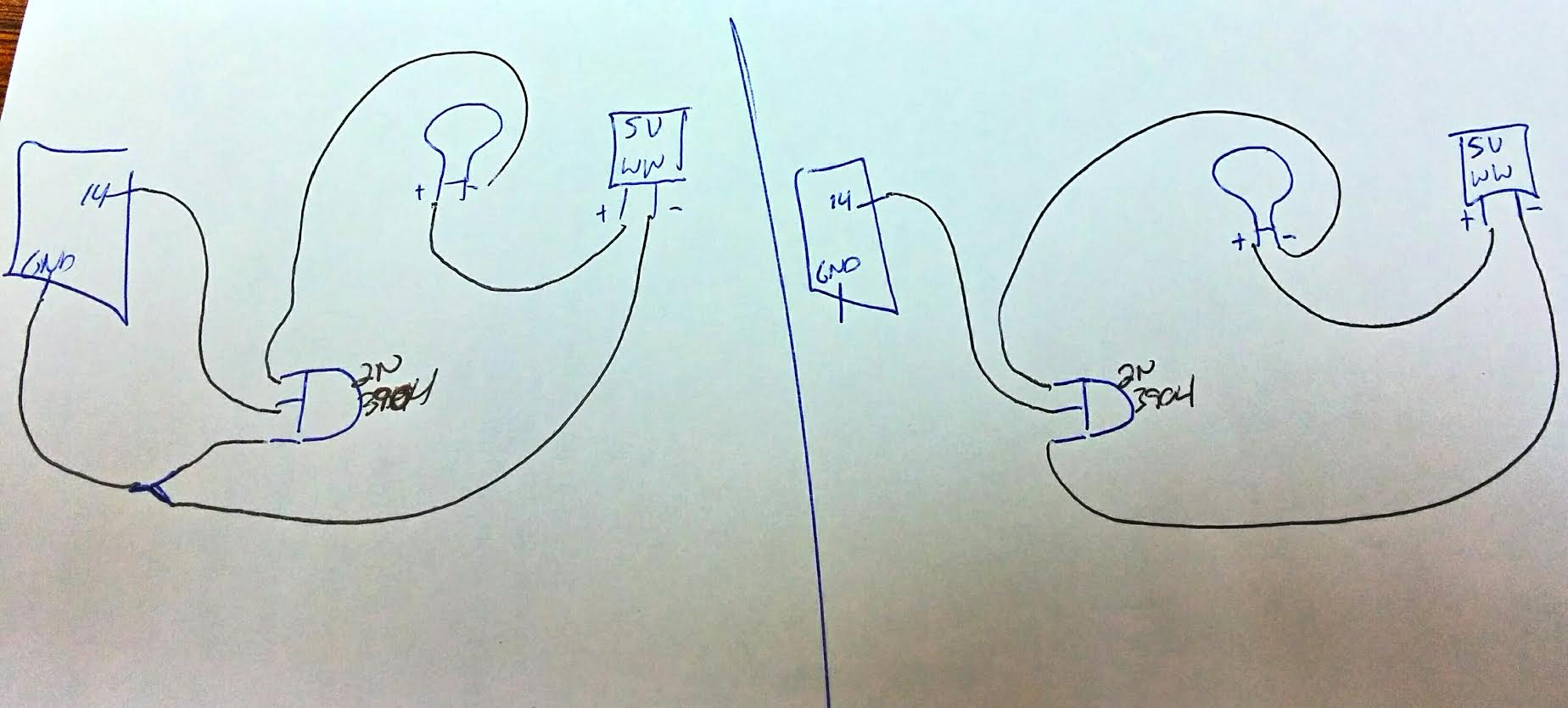
Work went late last night so I didn't get to try it out. I'm attaching a hand drawn schematic; the left is what I understand ChillTronix's suggestion to be; the right was what I had originally, which was relying only on the 5v ground. As I understand it, I should have a base resistor between the pin and the transistor. I could also have a resistor between the 5v and the lamp, but there's either one already built into the lamp, or they're just running without them when on battery power.
Yes, the code loaded onto the arduino is just a simple blink on 14 sketch. The code shown on the virtual breadboard printout is a full set of code, which has all 5 lights running the proper sequence and timings (-1 I broke off just to make sure I knew my pos/neg leads). Once this works, I'll do the same for the remaining for lights/transistors, and get the whole code on the arduino.
My transistor is a 2n3904.
Lamps are 9led flashlights from the dollar store, which run on 3aaa batteries in a handy battery pack. I soldered leads to the ends of the battery pack, and broke them out through a hole on the unit itself. It works fine if directly attaching the leads to +/-.
Everything's broken out and soldered into RCA leads, using couplers to quick attach leads to each other. To common the grounds, I'll use an rca Y adaptor (2-->1). I have an abundance of old rca cables, and they're cheap.
Hi, can you repost the circuit diagram with e b and c leads marked on the item representing the transistor.
Also you need a resistor between the transistor base and the output of the arduino, 4K7 will probably be enough.
Do not be surprised if the transistor is now faulty due to no base resistor being used.
I am assuming that they are not LEDs, but globes, that is incandescent lights.
There is a difference in how you drive lamps and LEDs.
Your transistors are wired backwards. The 2n3904 is left to right E , B, C. Your schematics show them wired backwards. The collector should be wired to the led , not the emitter. You first drawing shows the flat face
of the transistor facing the viewer, which means the emitter should be the first pin from the left, which should go to ground.
LINK: