Good day everyone, I am an electronic newbies and have some quetion on creating the transistor circuit.
Transistor Used : S8050
Controller Used : Arduino Uno
LED used : 5V with 650mA maximum current
I'll explain what I know. If i misunderstand something please guide me. I have attached a schematics.
From the things i understand. The voltage rating of the transistor isn't a problem because all of the transistor have a high voltage rating nearly 20~45V.
However, the Ic, collector current is the things i concern. The collector current shouldn't be lower that 650mA. I found a some datasheet showing the Ic is 700mA and some is 500mA, why? But let's assume that the Ic is 700mA.
Third, I also found the current rating of the output pin of arduino have a maximum of 40mA but recommend is 20mA. So i will assume the output current of Arduino pins is 20mA.
How will you limit current through the LED? You need either a 3W, very low resistance resistor, a linear constant current driver, or a switching constant current driver.
How will you power it? If you're driving the LED at full 650mA, you need an external power supply for it, as an Arduino board will give you 500mA max.
Why are you using BJTs instead of MOSFETs? MOSFETs are much better switches than BJTs. Dirt cheap fets with unreal current handling capability are readily available (eg, dime-sized TO-263 package handling tens of amps, rice-grain sized SOT-23 package handling 6A).
The output current of an arduino pin can exceed 40mA. It will try to drive to ground (0v) or Vcc (5v, normally), and if you're trying to drive something that would draw a lot of current, or that is shorted to the opposite power rail, the current will exceed 40mA; this is how you blow pins.
My current favorites are DMG3415 and DMG6968. Great current capability characterized down to 1.8V VGS and clamping diodes on the gate to protect against static discharge when handling them.
I apologize, actually i didn't plan to post this quetion because i haven't finish editing it. I will update it here now and explain again. But first, replies.
Replies:
DrAzzy : I am still learning how to use the transistor corretly. I will definitely consider the MOSFET after i am familiar with the BJT. Well, it's correct that the Arduino will supply 40mA current. But please keep reading. I tried to solve the problem with some resistor. Thanks.
Jiggy-Ninja: Thanks ! I'll check them out.
CrossRoads: Thanks ! I'll check them out too.
Continued post:
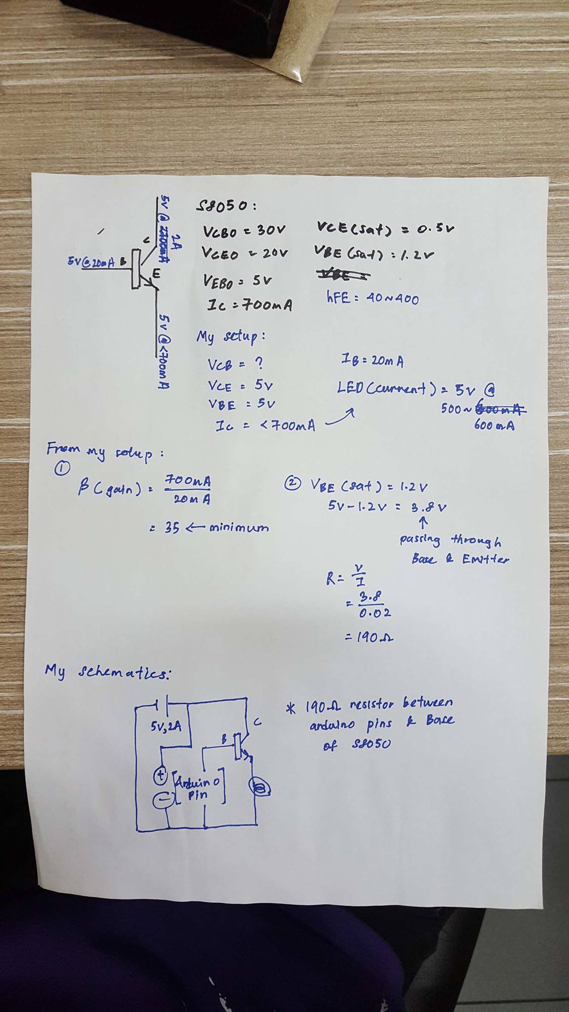
I uploaded a photo of my calculation for the transistor.
In the photo, i left one calculation.
Gain = 40, Ib=20mA . Applying the formula B(gain)=Ic/Ib. I'll get the Ic at 0.8A which over for my need. But since I can add a resistor of
Quetions:
Does Ic, collector current mean the maximum input current ? or it's the maximum current that can pass through the transistor. Eventhough i supply 2A to the transistor, it won't blow the transistor out as long as I control my base current so that the current flow though is lower than 700mA or my load current draw doesn't exist 700mA. Am i right ?
I calculated the DC current gain value of the the desired transistor using the maximum current draw of my load. The value is 35 and the minimum DC current gain of the S8050 is 40. So i assumed that i could use this transistor since i can limit the base current.
Then, i calculated the base pin resistor value using ohm's law. The base-emitter saturation voltage is 1.2V maximum. From my understanding the saturation voltage is = voltage drop between the point. So i used my base pin voltage which is 5V from a arduino and - with the saturation voltage (1.2v). By using ohm's law i get the value of 190ohm resistor.
But since the gain value of the transistor is 40, i need to recalculate my resistor value. First 40(gain)=700(Ic,the current i want)/Ib(the current that should given to the base current) and i get the ans of Ib with value of 0.018A. Using ohm's law again, I calculated the resistor value which is 210ohm(3.8V/0.018A = 210ohm)
Is there any problem with my schematics ? Since i am using a same power supply for my arduino and led (load) that i want to power, I am worried that i connected the circuit wrongly and will cause a short circuit. And then another thing came to my mind, is it a better choice to control the GND pin of my LED which mean i connect my postive terminal of the power supply directly to the LED and only controlling GND pin. Is this better or it's just the same ?
The transistor configuration you have used is called an emitter follower. It has a voltage gain of exactly 1, it is not dependant on the transistor's Hfe or what you consider as a gain.
You are misunderstanding how a transistor works and are applying calculations to that misunderstanding. The current between collector and base is largely determined by the load when a transistor is in switching mode which is what you want to do in digital electronics.
Your load looks like a flashlight bulb to me. If it is an LED you should use the correct symbol and also use a current limiting device like a resistor. But, if you are thinking of passing 700mA through an LED then you have a power LED and need to use a constant current supply to drive it, not what your diagram shows.
sooncheng:
LED used : 5V with 650mA maximum current
An LED with a 5V forward voltage? Really? Unlikely, but how can we check if you don't provide
the information we need - all the part numbers/datasheets of everything you have please, we
cannot guess such things, your job is to provide this.
If the LED is genuinely 5V forward voltage you cannot run it from 5V supply since there is no
means to stabilize the current without some voltage overhead to allow constant current circuit
to work.
Your schematic is wrong, the load goes on the collector, not the emitter.
What kind of LEDs? You're wasting a lot of peoples' time as they go off giving you advice as you made it sound like you have a single high-power LED which does need a constant current driver, but if you've been talking about an LED strip this whole time, it may already be current controlled and you just need to give it the right voltage.
You need to give the most basic of info. What kind of LEDs? How many?