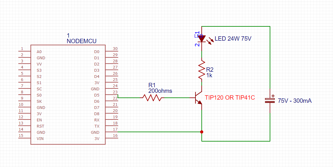
I made this project, I put the code below, but when I plug it in, the transistor gets very very hot! If it stays for 1 minute, the transistor stops working, how can I make a working dimmer? p.s. 75v is DC
int led = 14;
int brilho = 0;
int fade = 5;
void setup() {
  Serial.begin(115200);
  pinMode(led, OUTPUT);
}

void loop() {
  Serial.println(brilho);
  analogWrite(led, brilho);
  brilho = brilho + fade;
  if (brilho == 0 || brilho == 255) {
    fade = -fade ;
  }
  delay(150);
}
Very likely you are dissipating a lot of power in the transistor, with a few watts it will get very hot in no time. Does it have a heat sink? It will be much more efficient if you use PWM to control the brightness instead of linear control. It is a good practice to add a series resistor to the leds, so they dont burn.
You cannot drive a TIP120 very well with a NodeMCU.
The base of the TIP120 must be above 2v before the transistor even starts to turn on.
In addition, the TIP120 is a darlington transistor, not good for ON/OFF operation.
As @LarryD stated, you should use a MosFet that can be driven fully ON with a gate voltage of 3V.
This might be difficult to find such a MosFet with a Vds capability of 100V (you should not use a MosFet with a Vds at or near your 75V power supply.
Question: Is your ESP32 board powered by 5V? i.e. do you have 5V you can use? Or better yet 6 to 10 volts.
no not as your current device is connected.
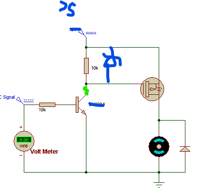
yes if you do the below circuit.
This is a Pchannel MosFet which means the source would be connected to your 75V, the drain to your LED and you would have to control the gate with a small NPN transistor or Nchannel Mosfet.
Something like this:
Where:
the blue is a 10 to 15V zener diode
the green is a resistor of something in the order of 10k (have not calculated it)
Why do you say this? None of it is not true!
TIP120 is a power (Darlignton) transistor designed for (ON/OFF) swithching applications.
As it is a Darlington it needs its Base about two BE junctions above Emitter - about 1.5V.
The schematic from OP should work:
The Base current is about (3.3 - 1.5) V / 2k2 ~ 0.8 mA. From the typical characteristic graph even 0.5 mA
should be able to switch 2A. Of course this is only typical graph, OTOH we want only 300 mA.
According to the same graph the CE voltage should be about 1 V. At 300 mA this is 300 mW. The transistor may be warm but shouldn't be hot. I believe there must be a problem elsewhere. (But I would use something like 1k for R1 just to be sure. Or 200R as shown on the other picture.)
Of course the circuit cannot work with TIP41 because it is not a Darlington.
You should post a picture of your circuit and some info about the used LEDs and the power source. I think most LED strips has current limiting resistors included. But strips I know are designed for less than 75 V.
Are the LEDs on or off? Does the dimming work (until the transistor fails)?
Maybe because this device is a poor choice for such an application. And if one did get it going there would not be much design margin.
Now a question for you. Why isn't is working in the OP's circuit? If what you say is true 3V and 200 ohms should turn on enough to keep the dissipated power to a minimum.
No, it is not a poor choice - it is a tradeoff between simplicity and efficiency. By "wasting" 300 mW you have much simpler circuit than your abomination in post #13. Which by the way consumes even more power. Just the nearly invisible green resistor will dissipate over 300 mW, not considering other parts of the circuit.
I am sorry I cannot find my crystal ball just now. I may only guess:
The TIP120 is fake and it is a single BJT such as TIP41.
There is a problem with the power source. Maybe it is a constant current source?
The LEDs do not include a current limiting resistor and only the weak Base drive provide current limiting.
There is a poor connection between Arduino GND and TIP120 Emitter which causes non-negligible voltage drop.
OP did not post anything since the schematic showing 200 Ohm R1. Maybe they tried it and it works?