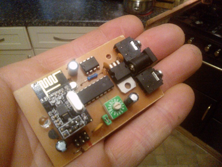
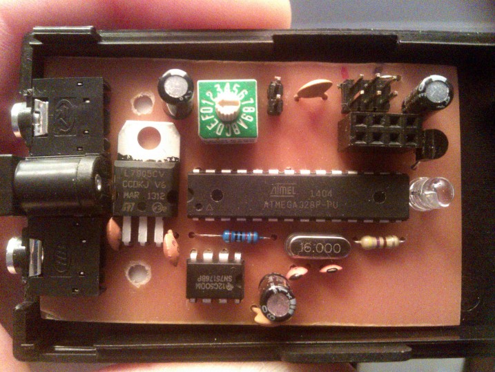
This is a very simple (but working) 512 channel wireless DMX.
I have removed all the bells and whistles out of the code for this one and just left what actually works on a single channel
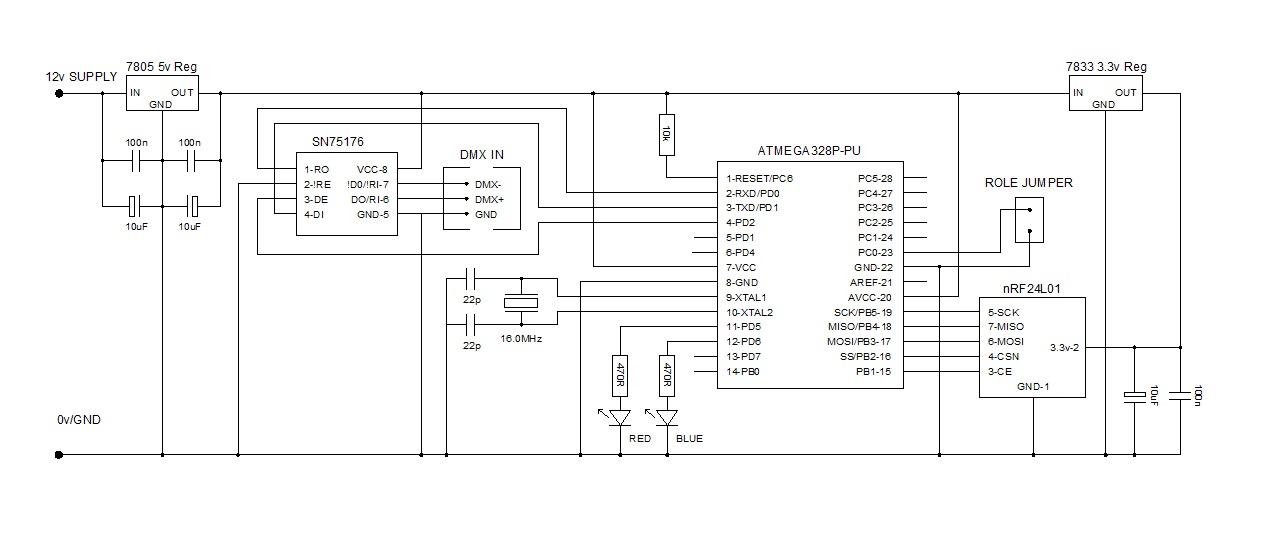
It is one piece of code that does both jobs, the role decided on if A0 is grounded or not
If A0 = grounded, the role will be a Wireless Reciever -> DMX transmitter
If A0 = high (or left pulled up) the roll will be a DMX receiver -> Wireless transmitter
I have left control of the RS485 interface chip via pins (or at least one pin) on the micro, so this changes the data flow direction
The code is set to channel 0 for both
On powerup, the Wireless transmitter will light a RED LED, if there is DMX coming in, this RED LED will flash
On powerup, the Wireless receiver will light a BLUE LED, if there is wireless being received it will flash
The DMX data coming in is compared with the previous DMX data channels and ONLY IF there has been data change will the final packet be sent for that group.
Every second ALL the DMX data is sent regardless of change. The radio data is sent virtually end to end without any breaks to give a nice smooth data flow
// FOR ATMEGA328 16mhz ONLY //
//
// NRF24L01 connection information : http://arduino-info.wikispaces.com/Nrf24L01-2.4GHz-HowTo
// Ensure 3.3v is used to supply NRF24L01 board !!
//
// SN75176 configuration :
//   DMXrx/NRFtx : pin 2 = 0v | pin 3 = 0v
//   NRFrx/DMXtx : pin 2 = 0v | pin 3 = 5v
//   pin 6 = DMX+
//   pin 7 = DMX-

#include <SPI.h>
#include <nRF24L01.h> // library: https://github.com/maniacbug/RF24
#include <RF24.h>
#include <Wire.h>
#include <DMXSerial.h> // library: http://www.mathertel.de/Arduino/DMXSerial.aspx //

#define MAX_DMX_CHANNELS 512 // full DMX
#define BYTES_PER_PACKET 16 // usable bytes per packet
#define PACKET_OVERHEAD 2 // group and time stamp
#define MAXPAYLOAD (BYTES_PER_PACKET+PACKET_OVERHEAD) // max payload size for nrf24l01
#define MAXGROUPS (MAX_DMX_CHANNELS/BYTES_PER_PACKET) // 32 groups of 16 channels = 512 DMX channels

// nRF24L01 control
#define nRF_CE 9 // Chip enable
#define nRF_CSN 10 // Chip select not
// sn76175 control
#define DMX_NOT_EN 2
#define DMX_MODE 3
// LEDs
#define LED_BLUE 6 // BLUE PWM
#define LED_RED 5 // RED PWM
// other
#define ROLE A0 // if low (jumper on) then RX otherwise TX

RF24 radio(nRF_CE,nRF_CSN);

unsigned long refreshTimer, flashTimer;
uint64_t RXTXaddress = 0xF0F0F0F0F0LL;
uint8_t RXTXchannel = 0;
uint8_t payload[MAXPAYLOAD], shadow_DMX[MAX_DMX_CHANNELS];
uint8_t timeStamp;
boolean group_send;

void setup(void)
{
  // set DMX/rs485 interface
  pinMode(DMX_NOT_EN, OUTPUT);
  digitalWrite(DMX_NOT_EN, LOW);
  pinMode(DMX_MODE, OUTPUT);
// other
  pinMode(ROLE, INPUT_PULLUP);
  pinMode(LED_BLUE, OUTPUT);
  pinMode(LED_RED, OUTPUT);
  radio.begin();
  radio.setAutoAck(false);
  radio.setPayloadSize(MAXPAYLOAD);
  radio.setPALevel(RF24_PA_HIGH);
  radio.setDataRate(RF24_250KBPS);
  radio.setRetries(0,0);
  radio.setChannel(RXTXchannel); // set the channel
  DMXSerial.maxChannel(MAX_DMX_CHANNELS);

  if (digitalRead(ROLE)) { // Jumper OFF : this is a wireless transmitter
    digitalWrite(DMX_MODE,LOW); // enable rs485 for input
    DMXSerial.init(DMXReceiver); // enable DMX to receive
    radio.openWritingPipe(RXTXaddress); // set network address
    radio.stopListening(); // start talking !
    digitalWrite(LED_RED,1); // Red ON
    digitalWrite(LED_BLUE,0); // Ground Blue Side of LED

  }
  else { // Jumper ON : this is a wireless receiver
    digitalWrite(DMX_MODE,HIGH); // enable rs485 for output
    DMXSerial.init(DMXController); // enable DMX for output only
    radio.openReadingPipe(1,RXTXaddress); // set network address
    radio.startListening(); // start listening for data
    digitalWrite(LED_RED,0); // ground Red side of LED
    digitalWrite(LED_BLUE,1); // Blue ON
  }
  refreshTimer = flashTimer = millis(); // start timing for DMX refresh on TX
}

void loop(void) {
/////////////////////////////// DMX IN --> WIRELESS TRANSMITTER ///////////////////////////////
  if ( digitalRead(ROLE) ) { // Jumper OFF : if a wireless transmitter
    for (uint8_t group = 0; group < MAXGROUPS; group++) { // send groups of DMX data, 16 bytes at a time
      uint16_t group_ptr = group*BYTES_PER_PACKET; // create group pointer for array
      if (millis() - refreshTimer > 1000) { // allow ALL radio data (full DMX array) to be send once per second, regardless of changes
        group_send = true; // force ALL send
        refreshTimer = millis(); // reset refresh timer
      }
      else {
        group_send = false; // preset flag to false, only set it if there has been a data change since last time
      }
      for (uint8_t chan = 1; chan < BYTES_PER_PACKET+1; chan++) {
        if ( DMXSerial.read(group_ptr+chan-1) != shadow_DMX[group_ptr+chan-1] ) { // compare test : current DMX against old DMX
          shadow_DMX[group_ptr+chan-1] = DMXSerial.read(group_ptr+chan-1); // if changed, update shadow array of DMX data and payload
          group_send = true; // set flag so that THIS group packet gets sent
        }
        payload[chan+1] = DMXSerial.read(group_ptr+chan-1); // ensure ALL up-to-date data gets through on this packet
      }
      if (group_send) { // only send the data that has changed, any data change in a group will result in whole group send
        payload[0] = group; // set first byte to point to group number (groups of 16 bytes)
        payload[1] = timeStamp++; // second byte helps us monitor consistency of reception at receiver with a continuous frame counter
        radio.write( payload, sizeof(payload) ); // dump payload to radio
      }
    }

    if ( (DMXSerial.noDataSince() < 2000) && (millis() > 1000) ) { // if DMX has been received within the last 2 seconds make LED flash
      if (!(millis() & 0b1100000000)) {
        digitalWrite(LED_RED,1); // flash ON
      }
      else { // flash OFF
        digitalWrite(LED_RED,0);
      }
    }
    else { // no DMX data present, no flash just ON
      digitalWrite(LED_RED,1);
    }

  }

/////////////////////////////// WIRELESS RECEIVER --> DMX OUT ///////////////////////////////
  else { // Jumper ON : if a wireless receiver
    if ( radio.available() ) {
      radio.read( payload, sizeof(payload) ); // get data packet from radio
      for (uint8_t i = 0; i <BYTES_PER_PACKET; i++) {
        DMXSerial.write((BYTES_PER_PACKET*payload[0])+i, payload[i+2]); // parse radio data into dmx data array
      }
      if (millis() - flashTimer < 750) {
        digitalWrite(LED_BLUE,0);
      }
      else if (millis() - flashTimer > 749) {
        digitalWrite(LED_BLUE,1);
      }
      if (millis() - flashTimer > 1024) {
        flashTimer = millis(); // reset timer after 1 second(ish)
      }
    }
  }
}