What if the person is on the left or right of the robot? I ask because you only mention forward or backward.
In my logic I guess it works in any position with 3 anchors.
I thought about that, it is the simplest after thinking about it, but, it is inefficient and will cause the robot to look crazy when making an inaccurate movement, it is better to go straight to the direction of the person.
You are asserting that if three anchors must be located within, say, an X by Y rectangle (to fit the available space on the rover), then placing them all in a line, say parallel to the longest direction (X or Y), or along the diagonal, is the optimum configuration for...what? Location accuracy... or code size... or both? Got proof?
If you want to save the cost and complexity of an additional (3rd) anchor, then you must make some compromises. (And I would say that even with three anchors, it WILL look a bit crazy, judging from that video. I doubt the third anchor will help much to reduce the effect of distance errors and the resulting erratic left/right movements.)
Of course. I was hoping @anon22423185 would realize that when trying to explain his claim that having them in a line is some sort of optimum.
Edited to add: I guess the reason I didn't mention it is that I'm more interested in the general question of the optimum location of three anchors in a rectangle with long side X, short side Y, and proportion Y/X, to minimize the error in calculated location of a tag in a certain area around the collection of sensors. It's clearly not with the anchors "on a line."
But is it with an anchor in the two corners separated by X, with the 3rd in the center of the opposite long edge?
Or is it with an anchor in each of three corners?
Some other solution?
Is there one solution that is optimum for all proportions Y/X?
As mentioned, obviously, as Y/X goes to zero, the arrangement becomes more linear, and eventually resolving the "which side of the line is the tag on" becomes impossible.
Well... The proof is the law of cosine, tangens and
I spend my days calibrating electronic-shooting ranges. There we triangulate the bullet with unknown x/y but thats more complex since its a Mach-cone. However to triangulate a not moving source in realtime the equation is pretty basic.
1 P emitting a signal.
2. Sensor1 gets the signal at time X1
3 Sensor2 get the signal at timeX2
4 The angle from the sensorline with respect to P is tangens of DTimeX*Speed of sound/Light ..
5 The third sensor is just to get a "null" to start counting and it gives you a second angle . the third sensor has to be hit first. Therfore the line.
@DaveEvans ....Every line in a square, triangle or any shape is....a line. So the equations is thesame regardless where u put the sensors.
The most opimized arrangement is however
four sensors with one in each corner.
1.1 If only three sensors put them in a L shape.
Surely it can be done with 2 sensors? Make the assumption that the target is at the position in front of the robot and begin moving the robot forward while continuing to triangulate the target. After a short time it will be clear if the robot is moving towards the target or not. If the target gets closer, the assumption was correct. If it gets farther away, the assumption was incorrect. The robot now knows the true position of the target. That should work, right? Assuming the target is stationary...
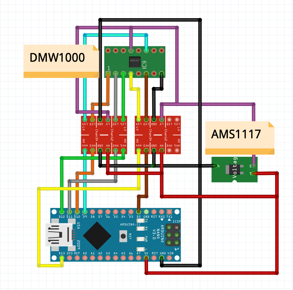
The tutorial says that 5V should be used, what should I do? I think the nano only offers 3V on the output of the "VIN" pin.
The tutorial says that pin 13 should be used, but the arduino nano doesn't have pin 13, so I changed it to pin 8... and the pin that the tutorial says should go to 2 I put it on pin 7. Will those work well?
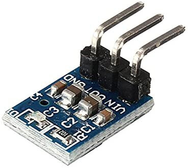
The tutorial says that I should use "AMS1117 3.3V DC Power Supply Module". I bought this: Amazon.com
(It has the same model, but it is different). What connections should I make? Since that only has 3 pins and the one in the tutorial has 4 (although the tutorial only has 3, it confuses me).
It has 3 pins, VIN (red), OUT (purple), GND (black). Are my connections correct?
2- I put the connections on the exact pins that the tutorial says: 13, 12, 11, 10, 9, 2. Will everything work fine? (I ask because I use Nano and the tutorial is ONE).
3- I'm really going to appreciate being told if I have a mistake.