Hello!
I am in need of some assistance, as I am trying to combine two open source FPGA projects into one. Those being the and The neoTRNG and the JTAG Interface made by @herrnamenlos123. I currently connected the two together in a BDF Schematic file as I lack the knowledge and know how of how VHDL code and Verilog code work. I was doing this to try to utilize the collection of the numbers generated to then be communicated via the Jtag Interface to the MCU.
With this in mind, I was able to “successfully” get the bitstream to load in using the JTAG Interface, however I do not know how successful it was as I am not receiving the number generated from the arduino via serial communication.
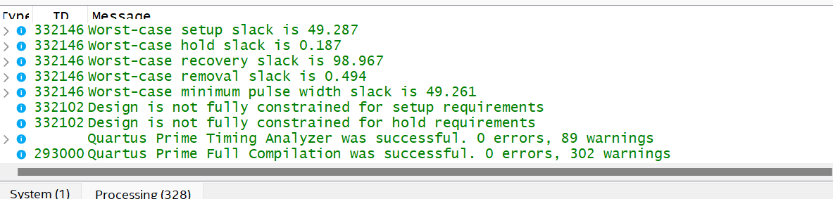
I have provided the number of warnings I am receiving and the visualization of the BDF schematic. If you have any thoughts or know how on which way I should go to establish a better communication or if I am missing something it would be greatly appreciated!
I am also using the 18.1 version of quartus as all the newer versions limit or prevent you from using VHDL code.
Hi, I am the Author of the JTAG_Interface library.
First of all, I can't see every part of the schematics because something seems to be wrong with your font size, no Idea I never had this issue.
Now, you connected the TRNG Output to an Input of the Jtag Interface. It seems like the Output says [7..0], which means it's 8 bit and the JTAG Interface is set to 32 bits, meaning it takes [31..0]. This shouldn't be possible to connect directly and should result in a compiler error, because it doesn't know what to do with the remaining 24 bits.
One Solution you could try is to split the conmection to ground. You can do this by connecting the two terminals to GND with a thick wire, and naming them (by selecting and starting to type). You can name the trng output "A[7..0]", the JTAG input to "A[31..0]" and the part that goes to GND "A[31..8]". (the same wire has 3 different labels in different locations). That way you can say the lowest 8 bits are the trng value and the other 24 are GND or 0. Keep in mind that this will not work for signed integers, if you try to read an 8 bit number as a 32 bit number (google zero-extending and sign-extending).
It works the same for Outputs, just that not all Output bits need to be connected.
Another, easier solution would be to simply set the JTAG parameter to 8 bits and only work with 8 bit numbers. Do not forget to also tell the Arduino Code that it's now 8 bits instead of 32.
That should be all that's required, assuming that TRNG actually works.
If you are not sure it's even working, please try the unmodified Jtag Example. Then work your way from there doing small modifications.
To test, connect a constant value to the input (double click, type LPM_CONSTANT), set it to the same number of bits and choose a value. Test if you receive it. If you do, switch to the TRNG.
About the thing with VHDL - I don't think any version would prevent writing VHDL since it's an integral part of the IDE. You should update to the latest version and maybe try again.
Also I haven't used VHDL much but I would advise you to learn Verilog instead. I think it's quite natural to write once you understand that it's not code that runs sequentially, but instead you describe wires using code. Imagine Verilog being a BDF file, but you use text to describe which wire is connected to what. I found Nandland to be a good resource.
And lastly, to why you're not receiving values, It's probably either because the bits mismatch (8 and 32) and it's not actually compiling or uploading. Otherwise, it must be on the Arduino side.
As said I would advise you to start again from the example, using my ByteReverser from Github, using LPM_CONSTANT for testing, and verifying and uploading every step, to ensure everything works. Go in small steps until you get to the TRNG.