Dear community,
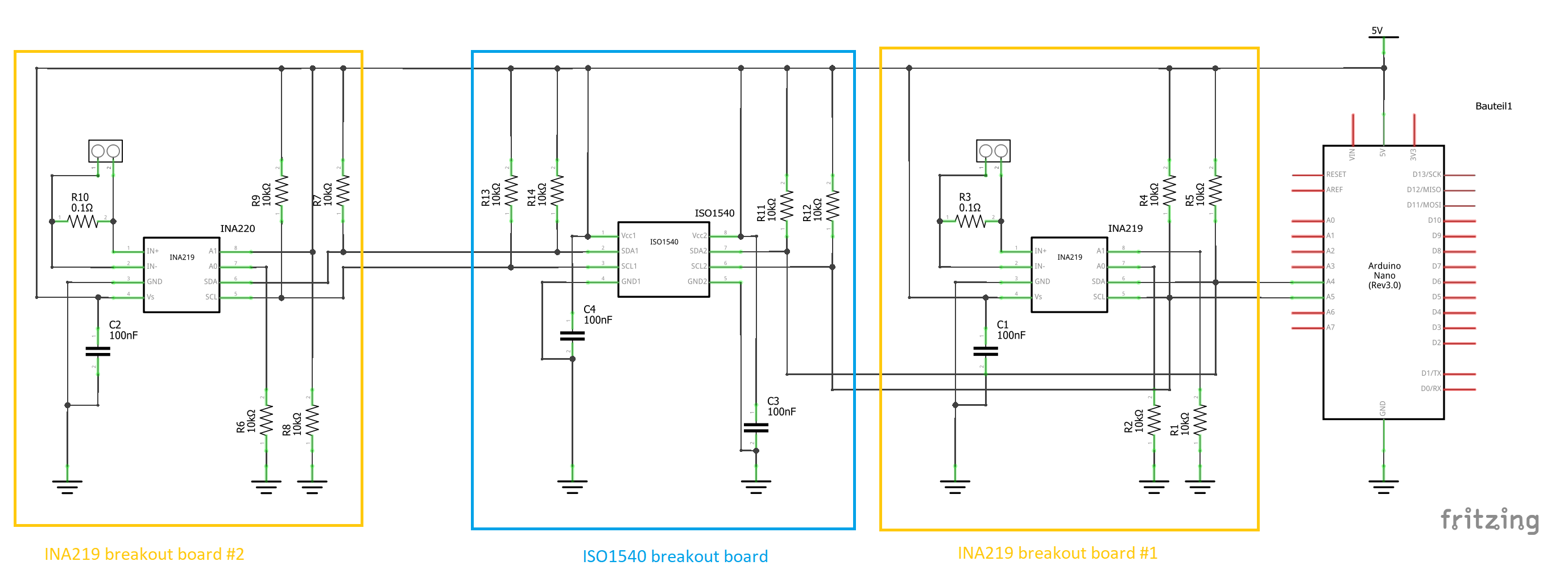
I am trying to isolate an I2C connection using ISO1540 (breakout from Adafruit) without any success.
I use:
- Arduino Nano
- 2x INA219 sensor breakout boards
- ISO1540 breakout
I power all components over USB.
What works
When I connect the INA219 sensors directly to the Arduino, they work like a charm (both with different I2C addresses).
What I need help with
Then I add the ISO1540 between the Arduino and one of the sensors. For testing purposes I use the same power supply (from Arduino Nano) on both sides of the ISO1540. As soon as I do this, the Arduino fails to connect to either sensor. The one behind the ISO1540 as well as the one directly connected to the Arduino.
Wiring seems to be correct as both power-LEDs on the ISO1540 breakout light up. As soon as i pull the SCL/SDA connection between the ISO1540 and Arduino, the other sensor is found again.
- Code appears to be correct, at least it works for both sensors directly connected to the Arduino. (I refrained from posting it as it is far from a minimal example and lots of other stuff and debugging messages in between).
- I am confident that the wiring is correct (at least correct pins connected).
I was hoping someone could point me in the right direction where to look:
- the INA219 breakouts as well as the ISO1540 (both sides) have onboard 10k pullups. -> is this a problem?
- INA219 and ISO1540 (both sides) also have a 0.1µF capacitor between ground and VCC
- I did not use any other components than these.
Furthermore, I have read that it might make a difference, which side of the ISO1540 is master and slave. Hence, I tested both directions without any luck
I was assuming that the ISO1540 would be a rather easy drop-in solution, but apparently it is not. What am I missing?
Any help would be appreciated,
Max