Hello,
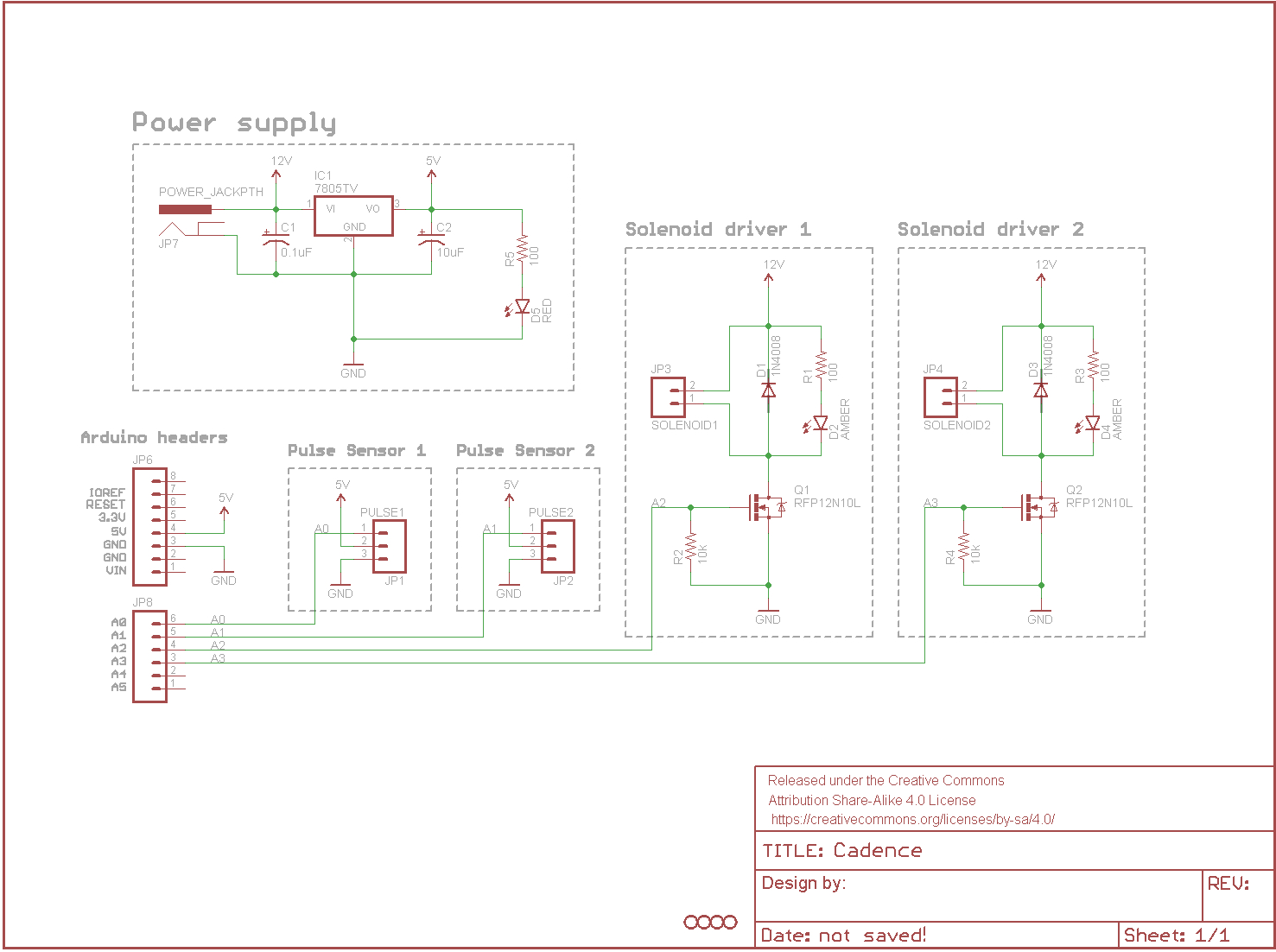
I'm working on a project where 2 heart pulse sensors trigger 2 solenoids (Sensor A triggers Solenoid A, Sensor B triggers Solenoid B) and is powered by one external power supply.
My friend drew up a schematic of what it should look like, but when I wired everything together it didn't work and now both of my pulse sensors don't seem to be working at all.
Could you please review the schematic and see if you can spot some flaw? Idk if the problem is the schematic, my wiring up of the circuit, or the code itself. Attached is the schematic, the code I'm using with the Uno, and a video of what the piece did when it was wired up. Any insight would be much appreciated. I'm debating if it's worth it to buy new sensors.... What could cause the analog input numbers from the pulse sensor to steadily decrease? It clearly is no longer receptive to changes in light.
You are passing the 5.2A ground return from the solenoids through thin traces and directly
routing these to the sensor grounds.
Ground and power traces need to be wide so they have low inductance, and also need to be
wide for high current as here.
Never use the same ground wiring for high current loads as sensors - run these separately
except at one common point, the Arduino ground pins. There should be a thick set of traces from where
the 12V + ground comes in to the solenoid loads. There should be separate traces for 5V and ground
to the sensors, so that transients on the high current wiring doesn't affect the sensor. This is
probably why they are dying.
Keep the sources of interference well away from sensitive analog wiring. Using analog pins to drive
out to the MOSFETs isn't a great move, you'll always get some crosstalk from traces that run side-by-side
especially without a ground-plane.
Ground planes are very useful, use them whenever possible. You ideally need two ground plane
sections here, one for sensors, one for high current load side of circuit.
You don't need 1200V freewheel diodes, 20V is plenty - they do have to take the 2.6A peak
current of the solenoids though.
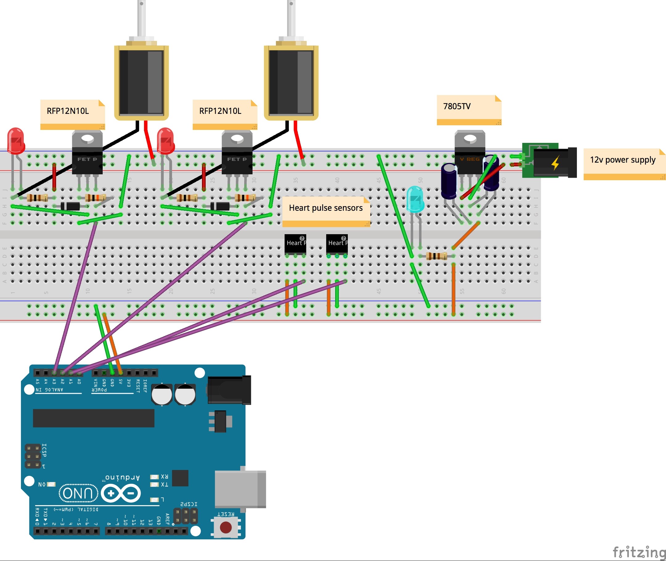
Well, generally we don't like Fritzing diagrams... So I can't say whether it is wired wrong. But if the Fritzing matches the schematic, I don't see any problems. (Keep in mind, just because the schematic or Fritzing is correct doesn't mean you wired it up that way.)
Those are some pretty big solenoids to run off of a breadboard, so you might want to find a different way. Maybe get some protoboard to solder the mosfets onto and use larger wire between mosfets/gnd/solenoids.
Your parts layout wouldn't change much with two ground planes and larger traces.
MarkT:
Your ground wiring is deeply flawed I'm afraid.
You are passing the 5.2A ground return from the solenoids through thin traces and directly
routing these to the sensor grounds.
Ground and power traces need to be wide so they have low inductance, and also need to be
wide for high current as here.
Never use the same ground wiring for high current loads as sensors - run these separately
except at one common point, the Arduino ground pins. There should be a thick set of traces from where
the 12V + ground comes in to the solenoid loads. There should be separate traces for 5V and ground
to the sensors, so that transients on the high current wiring doesn't affect the sensor. This is
probably why they are dying.
Keep the sources of interference well away from sensitive analog wiring. Using analog pins to drive
out to the MOSFETs isn't a great move, you'll always get some crosstalk from traces that run side-by-side
especially without a ground-plane.
Ground planes are very useful, use them whenever possible. You ideally need two ground plane
sections here, one for sensors, one for high current load side of circuit.
You don't need 1200V freewheel diodes, 20V is plenty - they do have to take the 2.6A peak
current of the solenoids though.
So does the ground for the sensor need to be attached to just the regulator and arduino? Should it not connect to the Mosfet at all?