Hello, guys
I have a Kamoer pump with its own 24V DC adapter and a control board that supports RS485 with MODBUS, and i'm trying to control it with an Arduino UNO.
The Arduino is connected to the PC through USB (receiving data through Serial, but that's for a later step).
I've connected the MAX485 to the Arduino like this:
RO->0
RE->1
DE->2
DI->3
VCC->5V
GND->GND
and to the pump controller like this
A->A
B->B

MAX485's led is on, so it appears to be working
I'm using <ModbusRTUMaster.h> since it can use the supported functions (other libraries don't seem to have the write single coil func) but i've tried others without success. ModbusRtu, ModbusMaster, ArduinoModbus...
I keep getting a Timeout Error with this and other libraries.
Here is the control board documentation:
board_23da3858-fb94-4ea4-82f1-616b8582b057.pdf (2.4 MB)
The important parts are:
-The pump address is 192 (0xC0) by default.
-Baud rate is 9600
-The supported feature codes are
0x05 - Write Single Coil
0x03 - Read Holding Registers
0x06 - Write Single Registe
0x10 - Write Multiple Registers
-"FIRST, YOU NEED TO SEND A COMMAND TO ENABLE THE 485. SENDING OTHER COMMANDS CANNOT RESPOND"
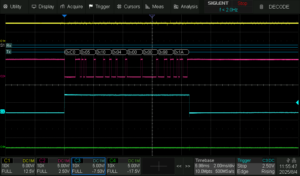
the command being 0x05 (the full message being "C0 05 1004 FF00 D9EA", but i don't know how to print the full hex string to check if it is correct)
I have tried using the slave id as 192 (the default pump id) and 0 for broadcast.
When using 0 i get no error but the pump does nothing.
After sending the enable command, i attempt to start and stop the pump in a loop, but i keep getting Timeout errors.
I cannot even try to debug reading holding registers because i cannot enable the pump's 485 communication successfully.
If i understand correctly, the Arduino's USB connection to the PC is Serial.
After a while i understood that the example codes i found tried to connect the MAX485 to Serial, which was wrong (or am i wrong about this too??), but surely i'm still missing something.
Here's my code
//https://github.com/CMB27/ModbusRTUMaster
#include <ModbusRTUMaster.h>
#include <RS485.h>

// The ATmega328P and ATmega168 only have one HardwareSerial port, and on Arduino boards it is usually connected to a USB/UART bridge.
// So, for these boards, we will use SoftwareSerial with the lbrary, leaving the HardwareSerial port available to send debugging messages.
///#include <SoftwareSerial.h>
const int8_t rxPin = 0;//ro
const int8_t rePin = 1;
const int8_t dePin = 2;
const int8_t txPin = 3;//di

///SoftwareSerial mySerial(rxPin, txPin);
//#define MODBUS_SERIAL mySerial

#define MODBUS_BAUD 9600

// 0 indicates a broadcast message.
// The default address is 192 (0xC0)
int SLAVE_ID = 0xC0; //0;

// SUPPORTED FEATURE CODES
//   Read:
// 0x03: Multiple Holding Registers (FC=03)
//   Write:
// 0x05: Single Coil (FC=05)
// 0x06: Single Holding Register (FC=06)
// 0x10: Multiple Holding Registers (FC=16)

#define COIL_485ENABLE 0x1004
#define COIL_STARTSTOP 0x1001

const uint8_t numCoils = 1;
bool coils[numCoils];

///ModbusRTUMaster master(MODBUS_SERIAL, dePin);
ModbusRTUMaster master(RS485, dePin, rePin);

uint8_t error;

const char* errorStrings[] = {
  "success", "invalid id", "invalid buffer", "invalid quantity",
  "response timeout", "frame error", "crc error", "unknown comm error",
  "unexpected id", "exception response", "unexpected function code", "unexpected response length",
  "unexpected byte count", "unexpected address", "unexpected value", "unexpected quantity"
};
const uint8_t numExceptionResponseStrings = 4;
const char* exceptionResponseStrings[] = {
  "illegal function", "illegal data address", "illegal data value", "server device failure"
};

void setup() {
  //Serial for printing to PC
  Serial.begin(9600);
  while (!Serial);
  Serial.println();

  pinMode(LED_BUILTIN, OUTPUT);
  digitalWrite(LED_BUILTIN, LOW); //led off

  //modbusSetup
  RS485.begin(MODBUS_BAUD); //, HALFDUPLEX, SERIAL_8E1);
  //MODBUS_SERIAL.begin(MODBUS_BAUD);
  master.begin(MODBUS_BAUD);
  delay(100);

  enablePumpCommunication();
  delay(1000);
}

void loop() {
  startPump();
  delay(1000);
  stopPump();
  delay(3000);
}

void enablePumpCommunication() {

  // "FIRST, YOU NEED TO SEND A COMMAND TO ENABLE THE 485.
  // SENDING OTHER COMMANDS CANNOT RESPOND"

  //C0 05 1004 FF00 D9EA
  Serial.println("---enableCommunication");
  error = master.writeSingleCoil(SLAVE_ID, COIL_485ENABLE, 0x01);
  printError(error);

  delay(100);

  // check if coil is ON?
  Serial.println("---read coil AFTER enable");
  // (unitId, startAddress, buffer, quantity)
  error = master.readCoils(SLAVE_ID, COIL_485ENABLE, coils, numCoils);
  printError(error);
}
void startPump() {
  digitalWrite(LED_BUILTIN, HIGH); //led on

  //C0 05 1001 FF00 C93B
  Serial.println("---startPump");
  error = master.writeSingleCoil(SLAVE_ID, COIL_STARTSTOP, 0x01);
  printError(error);
}
void stopPump() {
  digitalWrite(LED_BUILTIN, LOW); //led off

  //C0 05 1001 0000 881B
  Serial.println("---stopPump");
  error = master.writeSingleCoil(SLAVE_ID, COIL_STARTSTOP, 0x00);
  printError(error);
}
void printError(uint8_t error) {
  if (!error) {
    Serial.println("No error :)");
    return;
  }
  Serial.println("Error:");
  if (error < (16)) {
    Serial.print(errorStrings[error]);
    if (error == MODBUS_RTU_MASTER_EXCEPTION_RESPONSE) {
      uint8_t exceptionResponse = master.getExceptionResponse();
      Serial.print(exceptionResponse);
      if (exceptionResponse >= 1 && exceptionResponse <= numExceptionResponseStrings) {
        Serial.print(" - ");
        Serial.print(exceptionResponseStrings[exceptionResponse - 1]);
      }
    }
  } else {
    Serial.print("Unknown error: <" + String(error) + ">");
  }
  Serial.println();
}
Does anyone know why i keep getting a Timeout?
I don't have a USB-RS485 dongle for testing.