Hi,
I am trying to use an Arduino Uno R4 minimo as a modbus RTU slave
with the modbus shield from Zihatec as sold by Pi hut. Zihatec provide a
sample slave code and project introduction which I have followed closely.(https://www.hwhardsoft.de/english/projects/rs485-arduino/)
[Zihatec project instructions]
They also suggest a Modbus
master tester from schnieder but that web link is down every time I look.
But using other modbus master testers the tx led flashes on the shield
and RS485 converter synchronously but they always time out.
In the project instructions it says that you can access the status of the
push button in register 200008 and turn the LED on/of with register
200007. If I put either of these in the tester register number box there
are either not enough digits available or two others reset to 65535. can
anyone suggest what I am doing wrong?
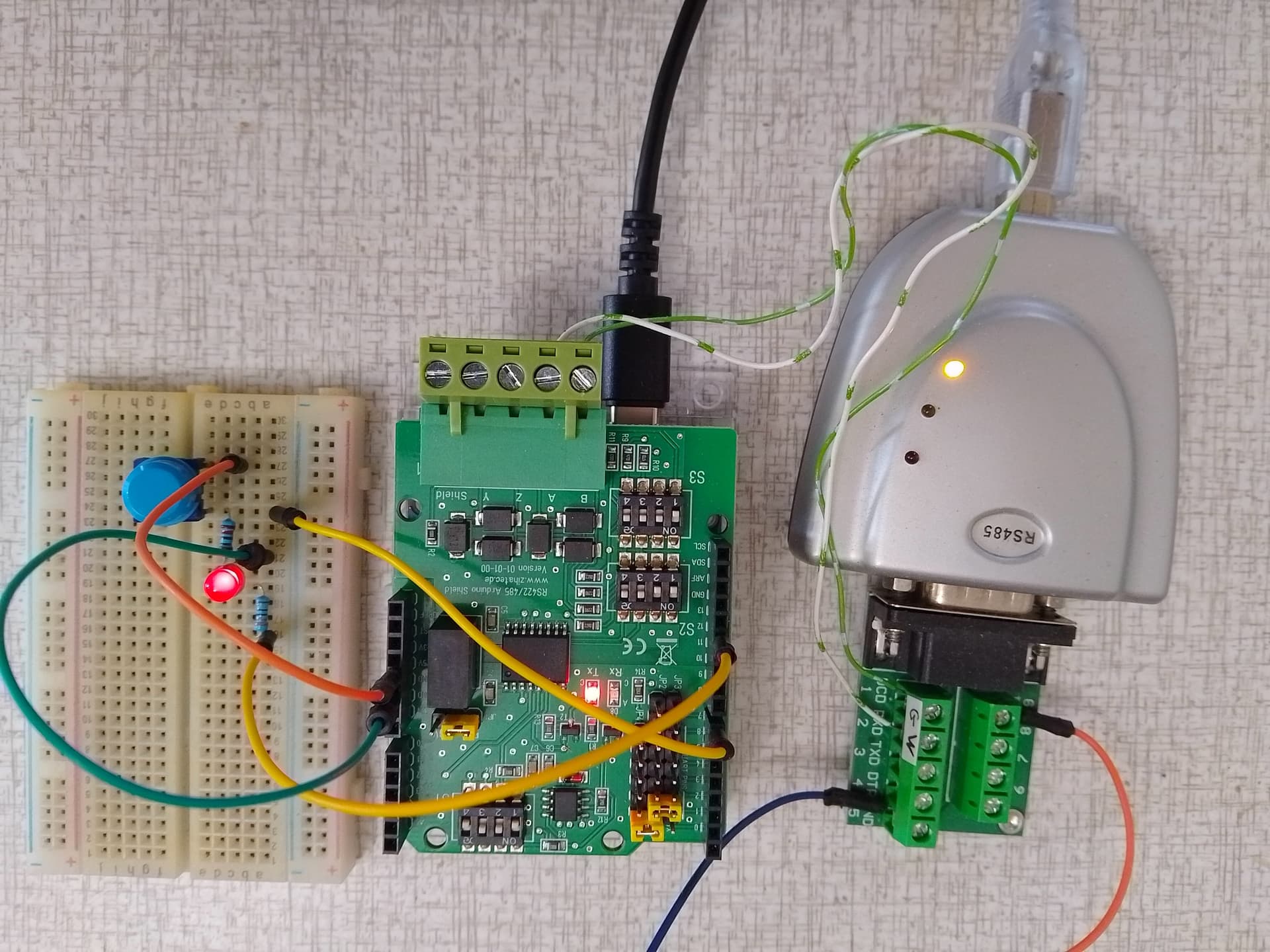
Here is a picture of my setup. The yellow wires do go into D7 and D12
just dont look like it because of paralax.

Here is the arduino code for the project
/*
* Test program for Arduino RS422/RS485 Shield
* for Arduino UNO and Software UART (recommended)
* Version 1.0
* Copyright (C) 2021 Hartmut Wendt www.zihatec.de
*
* (based on sources of https://github.com/angeloc/simplemodbusng)
*
* Settings:
* SW1: OFF, ON, OFF, ON
* SW2: OFF, OFF, ON, ON
* SW3: ON, OFF, OFF, OFF
*
* JP1: 5V
* JP2 - JP4:
* 0 ...
* 1 ...
* 2 .xx
* 3 xx.
* 4 ...
* 5 ...
* 6 xx
* 7 ..
*
* This program is free software: you can redistribute it and/or modify
* it under the terms of the GNU General Public License as published by
* the Free Software Foundation, either version 3 of the License, or
* (at your option) any later version.
*
* This program is distributed in the hope that it will be useful,
* but WITHOUT ANY WARRANTY; without even the implied warranty of
* MERCHANTABILITY or FITNESS FOR A PARTICULAR PURPOSE. See the
* GNU General Public License for more details.
*
* You should have received a copy of the GNU General Public License
* along with this program. If not, see <http://www.gnu.org/licenses/>.
*/
#include "SoftwareSerial.h"
#include "SimpleModbusSlaveSoftwareSerial.h"
#define buttonPin 7 // external push button (option)
#define RX 2 // pin D2
#define TX 3 // pin D3
#define RS485_EN 6 // pin D6 to set transmission mode on RS485 chip disabled
#define BAUD_RATE 9600 // baud rate for serial communication
#define deviceID 1 // this device address
SoftwareSerial rs485(RX, TX);
/* This example code has 9 holding registers. 6 analogue inputs, 1 button, 1 digital output
and 1 register to indicate errors encountered since started.
Function 5 (write single coil) is not implemented so I'm using a whole register
and function 16 to set the onboard Led on the Atmega328P.
The modbus_update() method updates the holdingRegs register array and checks communication.
Note:
The Arduino serial ring buffer is 128 bytes or 64 registers.
Most of the time you will connect the arduino to a master via serial
using a MAX485 or similar.
In a function 3 request the master will attempt to read from your
slave and since 5 bytes is already used for ID, FUNCTION, NO OF BYTES
and two BYTES CRC the master can only request 122 bytes or 61 registers.
In a function 16 request the master will attempt to write to your
slave and since a 9 bytes is already used for ID, FUNCTION, ADDRESS,
NO OF REGISTERS, NO OF BYTES and two BYTES CRC the master can only write
118 bytes or 59 registers.
Using the FTDI USB to Serial converter the maximum bytes you can send is limited
to its internal buffer which is 60 bytes or 30 unsigned int registers.
Thus:
In a function 3 request the master will attempt to read from your
slave and since 5 bytes is already used for ID, FUNCTION, NO OF BYTES
and two BYTES CRC the master can only request 54 bytes or 27 registers.
In a function 16 request the master will attempt to write to your
slave and since a 9 bytes is already used for ID, FUNCTION, ADDRESS,
NO OF REGISTERS, NO OF BYTES and two BYTES CRC the master can only write
50 bytes or 25 registers.
Since it is assumed that you will mostly use the Arduino to connect to a
master without using a USB to Serial converter the internal buffer is set
the same as the Arduino Serial ring buffer which is 128 bytes.
*/
// Using the enum instruction allows for an easy method for adding and
// removing registers. Doing it this way saves you #defining the size
// of your slaves register array each time you want to add more registers
// and at a glimpse informs you of your slaves register layout.
//////////////// registers of your slave ///////////////////
enum
{
// just add or remove registers and your good to go...
// The first register starts at address 0
ADC0,
ADC1,
ADC2,
ADC3,
ADC4,
ADC5,
LED_STATE,
BUTTON_STATE,
TOTAL_ERRORS,
// leave this one
TOTAL_REGS_SIZE
// total number of registers for function 3 and 16 share the same register array
};
unsigned int holdingRegs[TOTAL_REGS_SIZE]; // function 3 and 16 register array
////////////////////////////////////////////////////////////
void setup()
{
// enable hardware uart for debugging
Serial.begin(9600);
Serial.println("Init Modbus...");
/* parameters(SoftwareSerial* comPort,
long baudrate,
unsigned char ID,
unsigned char transmit enable pin,
unsigned int holding registers size)
The transmit enable pin is used in half duplex communication to activate a MAX485 or similar
to deactivate this mode use any value < 2 because 0 & 1 is reserved for Rx & Tx.
but practically it works with all major modbus master implementations.
*/
modbus_configure(&rs485, BAUD_RATE, deviceID, RS485_EN, TOTAL_REGS_SIZE);
pinMode(LED_BUILTIN, OUTPUT);
pinMode(buttonPin, INPUT);
}
void loop()
{
// modbus_update() is the only method used in loop(). It returns the total error
// count since the slave started. You don't have to use it but it's useful
// for fault finding by the modbus master.
holdingRegs[TOTAL_ERRORS] = modbus_update(holdingRegs);
for (byte i = 0; i < 6; i++)
{
holdingRegs[i] = analogRead(i);
delayMicroseconds(50);
}
byte buttonState = digitalRead(buttonPin); // read button states
// assign the buttonState value to the holding register
holdingRegs[BUTTON_STATE] = buttonState;
// read the LED_STATE register value and set the onboard LED high or low with function 16
byte ledState = holdingRegs[LED_STATE];
if (ledState) // set led
{
digitalWrite(LED_BUILTIN, HIGH);
Serial.print("Onboard LED is ON");
}
else if (ledState == 0) // reset led
{
digitalWrite(LED_BUILTIN, LOW);
Serial.print("Onboard LED is OFF");
holdingRegs[LED_STATE] = 0;
}
if (holdingRegs[TOTAL_ERRORS])
{
Serial.print(", Transmission Errors: ");
Serial.println(holdingRegs[TOTAL_ERRORS]);
} else {
Serial.println();
}
}
Not knowing details about the R4 I've picked up that it's quite different in some respects. The core is different and maybe the pinout is changed.
Check which controller it's made for. Just "UNO" is not good enough.
Check for which controller it's made for.
Please post the picture here. Downloading unknown material is No, No for many helpers.
I see, I will have to contact Zihatec to be sure that the R4 controller is compatible with their shield. I am trying to upload the photo but cant find out how just now. you would think it would be easy.
You have 9 holding registers, the adresses are 0-8 in hex (function 03) or 40001-40009 in dec.
looks like uploading an image only works in edits.
I might be able to understand that but the addresses are like 400007 in the guide, four zeros.
One zero error could be understandable, but you wrote:
Only slave library I have used is this:
At least with Esp32 it works like expected.
Uploading an image is just a matter if drag and drop of an image file in the composer or copy and paste an image in the composer. Just tested copy/paste. I did not need to edit my reply.

That would surely clear things up. The R4 is not like the old, reliable UNO R3. Sorry, not able to pinpoint details.
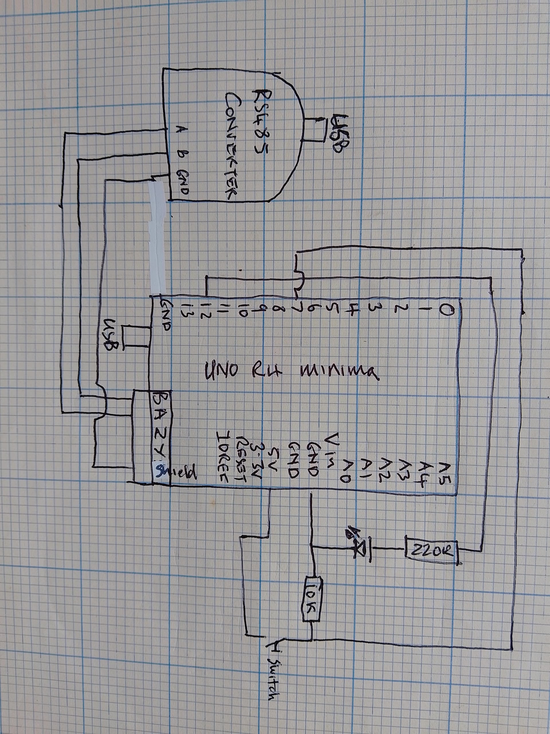
One tip: Using pen, paper and posting a picture of a hand drawn schematics including all power supplies is higly appreciated by forum helpers.
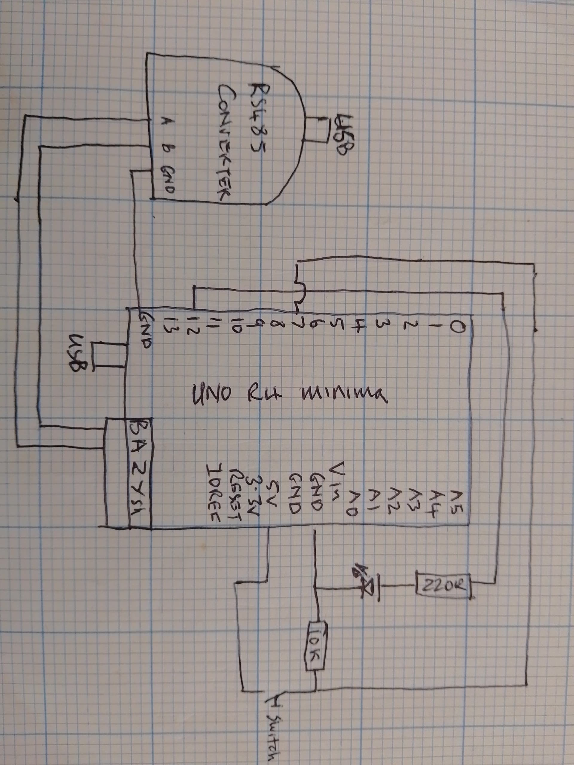
As requested. It shows a ground connection between Rs485 converter and Arduino that is not present in the photo. Clearly there is 5 volts (or so) at both USB connections from a common source.
The A to A resp B to B connections tells me nothing but the rest looks okey. Where and how does the RS485 cables connect?
Personally I would D7 as INPUT_PULLUP and the switch between D7 and GND. A low indicates the button is pressed.
A and B are the Rs485 bus, I have moved the ground again to the "shield" connection as indicated in manufacturer blurb.
Do you think the D7 and D12 should be swapped based on the code below where is says push button D12? Also this code is given to me by Zihatec and the suspicion that UNO R4 minima cannot be used with modbus is not justified due to various claims and examples available on the web. I have the Rx/Tx LEDs flashing synchronously on RS485 converter and the R4 but still have timeout error. I have all the parameters correct, Any suggestions please I have been trying to get this working with various Arduinos and Max units on and off for a year now.
/*
 *  Test program for Arduino RS422/RS485 Shield and Arduino R4
 *  Version 1.0
 *  Copyright (C) 2023  Hartmut Wendt  www.zihatec.de
 *
 *
 *  (based on sources of https://github.com/angeloc/simplemodbusng)
 *
 *
 *  This program is free software: you can redistribute it and/or modify
 *  it under the terms of the GNU General Public License as published by
 *  the Free Software Foundation, either version 3 of the License, or
 *  (at your option) any later version.
 *
 *  This program is distributed in the hope that it will be useful,
 *  but WITHOUT ANY WARRANTY; without even the implied warranty of
 *  MERCHANTABILITY or FITNESS FOR A PARTICULAR PURPOSE.  See the
 *  GNU General Public License for more details.
 *
 *  You should have received a copy of the GNU General Public License
 *  along with this program.  If not, see <http://www.gnu.org/licenses/>.
*/

#include "SimpleModbusSlave.h"

#define  buttonPin  12 // push button

/* DIP Switch setting for Arduino UNO R4:
 *
 *  S1: OFF-ON-ON-OFF
 *  S2: OFF-OFF-ON-ON
 *  S3: ON-OFF-ON-ON
 *
 *
 * Jumper Settings for Arduino UNO R4:
 *
 *  TX-RX:
 *  .XX
 *  XX.
 *  ...
 *  ...
 *  ...
 *  ...
 *  ..
 *  ..
 *
 *  5V - 3V
 *  XX.
 *
 *
 */


// Using the enum instruction allows for an easy method for adding and
// removing registers. Doing it this way saves you #defining the size
// of your slaves register array each time you want to add more registers
// and at a glimpse informs you of your slaves register layout.


//////////////// registers of your slave ///////////////////
enum
{
  // just add or remove registers and your good to go...
  // The first register starts at address 0
  ADC0,
  ADC1,
  ADC2,
  ADC3,
  ADC4,
  ADC5,
  LED_STATE,
  BUTTON_STATE,
  TOTAL_ERRORS,
  // leave this one
  TOTAL_REGS_SIZE
  // total number of registers for function 3 and 16 share the same register array
};

byte ledState=0; // led off
int  errors=0;   // communication errors


unsigned int holdingRegs[TOTAL_REGS_SIZE]; // function 3 and 16 register array
////////////////////////////////////////////////////////////

void setup()
{
  // init UART0 for debugging
  Serial.begin(9600);

  /* parameters(long baudrate,
                unsigned char ID,
                unsigned char transmit enable pin,
                unsigned int holding registers size,
                unsigned char low latency)

     The transmit enable pin is used in half duplex communication to activate a MAX485 or similar
     to deactivate this mode use any value < 2 because 0 & 1 is reserved for Rx & Tx.
     Low latency delays makes the implementation non-standard
     but practically it works with all major modbus master implementations.
  */
  delay(1000);
  Serial.print("Init MODBUS...");
  // inti UART 1 (D0/D1) for RS485
  // 9600 Baud, No Partity,
  // slave ID 1
  modbus_configure(115200, 1, 0, TOTAL_REGS_SIZE, 0);
  Serial.println("done!");

  pinMode(LED_BUILTIN, OUTPUT);
  pinMode(buttonPin, INPUT_PULLUP);

}

void loop()
{
  // modbus_update() is the only method used in loop(). It returns the total error
  // count since the slave started. You don't have to use it but it's useful
  // for fault finding by the modbus master.
  holdingRegs[TOTAL_ERRORS] = modbus_update(holdingRegs);
  if (errors != holdingRegs[TOTAL_ERRORS]) {
    errors = holdingRegs[TOTAL_ERRORS];
    Serial.print("Errors: ");
    Serial.println(errors);
  }
  for (byte i = 0; i < 6; i++)
  {
    holdingRegs[i] = analogRead(i);
    delayMicroseconds(50);
  }
  byte buttonState = digitalRead(buttonPin); // read button states

  // assign the buttonState value to the holding register
  holdingRegs[BUTTON_STATE] = buttonState;

  // read the LED_STATE register value and set the onboard LED high or low with function 16
  if (ledState != holdingRegs[LED_STATE]){
    ledState = holdingRegs[LED_STATE];

    if (ledState) // set led
    {
      digitalWrite(LED_BUILTIN, HIGH);
      Serial.println("ONBOARD LED ON");
    }
    else if (ledState == 0) // reset led
    {
      digitalWrite(LED_BUILTIN, LOW);
      Serial.println("ONBOARD LED OFF");
    }
  }
}
What does that tell?
Since you have good selection of hardware, I suggest you to build working setup with Arduino, Max485 and maybe even trying another library. When you have something that is working, it's easy to adjust the hardware.
It is working. On the shield there are dip switch settings for pull up resistor on B and pull down resistor on A together with automatic flow control setting and same on the master, I think that is what was wrong.
Also I looked at Kmin's advice from last year and changed the starting address of the registers to 0 having been told is was 400001 or 20001. Another source of error I now realise is that in some testers you cannot easily put zero as starting address so have to put 1 and then you are trying to read more than the specified number of registers.
Now can anyone explain how I could specify a value to output at the registers? they are in enum form as below so I dont understand, I cant just put ADC0 = 333 or something because ADC0 = 1 it seems?
//////////////// registers of your slave ///////////////////
enum
{
  // just add or remove registers and your good to go...
  // The first register starts at address 0
  ADC0,
  ADC1,
  ADC2,
  ADC3,
  ADC4,
  ADC5,
  LED_STATE,
  BUTTON_STATE,
  TOTAL_ERRORS,
  // leave this one
  TOTAL_REGS_SIZE
  // total number of registers for function 3 and 16 share the same register array
};
I agree, that library code is confusing, I suggested to use another one.
Anyway you can do:
holdingRegs[0] = 123;
holdingRegs[1] = 321;
...
Thanks, I appreciate your suggestion to move to a different library, do you think there is anything in this code that controls the automatic flow control. The code at the end, below, I guess just operates the indicator LEDs?
  // assign the buttonState value to the holding register
  holdingRegs[BUTTON_STATE] = buttonState;

  // read the LED_STATE register value and set the onboard LED high or low with function 16
  if (ledState != holdingRegs[LED_STATE]){
    ledState = holdingRegs[LED_STATE];

    if (ledState) // set led
    {
      digitalWrite(LED_BUILTIN, HIGH);
      Serial.println("ONBOARD LED ON");
    }
    else if (ledState == 0) // reset led
    {
      digitalWrite(LED_BUILTIN, LOW);
      Serial.println("ONBOARD LED OFF");
    }
  }
{
In this code there is nothing, flow control is disabled.
This topic was automatically closed 180 days after the last reply. New replies are no longer allowed.