Trying to drive a P-Mosfet, but it drives me crazy instead....

Hi,

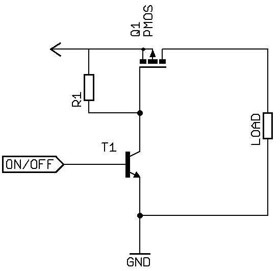
I'm trying to drive a p-mosfet Intelligent Power and Sensing Technologies | onsemi from pin #4 like so: Circuit Simulator Applet. The load is a step-up to 5v that feeds a 433MHz Tx.

I'm using an atmega328 on a breadboard at 8Mh, powered either from the arduino usb2serial adapter or a 1S lipo (4v2 - 3v7).

Well, when the pin gets low, if the bb is hooked to the usb2serial I get a couple of usb beeps and the IDE looses the virtual com port. Actually a little ago the usb2serial died!
If I replace the 220Ohm resistor with a 2.2KOhm resistor and the mosfet with a pnp transistor BC327, it works fine.

This is driving me crazy. Any help greatly appreciated.
The part of the code that drives pin 4:

...
#define TxPowerPIN             4
#define TX433PIN               12
...
void xmit(char *ck, char *hstring, char *tstring)
{
char *msgmask="%s,%02X,%s,%s,%s,%s";
  digitalWrite(TxPowerPIN,LOW); // Turn on the p-mosfet
  pinMode(TxPowerPIN, OUTPUT);
  delay(50);
 ADMUX = (0<<REFS1) | (0<<REFS0) | (0<<ADLAR) | (1<<MUX3) | (1<<MUX2) | (1<<MUX1) | (0<<MUX0);
 int value;

 for (int d=4; d>0; d--) { 
 // Start a conversion  
   ADCSRA |= _BV( ADSC );
 
 // Wait for it to complete
   while( ( (ADCSRA & (1<<ADSC)) != 0 ) );
 }// Repeat conversion 

 // Scale the value
// rawAnalogReadWithSleep();
 value = (((InternalReferenceVoltage * 1024L) / rawAnalogReadWithSleep()) + 5L) / 10L;

 //value = (((InternalReferenceVoltage * 1024L) / ADC) + 5L) / 10L;
//  float vin=((analogRead(VoltagePIN)/1024.0)*aref)*(r1+r2)/r2;
  float vin=(float)value/100.0;
  char msg[64];
  char vstring[10];
  dtostrf((float)vin,4,2,vstring);
//  dtostrf((int)value,3,0,vstring);
  sprintf(msg, msgmask, loc, cnt, vstring, ck, hstring, tstring);

#if DBUG > 0
 Serial.println(value);
  Serial.println(msg);
#endif

// Send Data 
  vw_send((uint8_t *)msg, strlen(msg));
//  vw_wait_tx();
//  delay(400);
  delay(200);
  cnt++;
//  digitalWrite(TxPowerPIN,HIGH);
  pinMode(TxPowerPIN, INPUT); //Return to hi-z, mosfet-off
}
...

Please post an image, not an applet.


Remove the 470uF and you'll have no problems.

If you are needing to switch a large capacitive load you'll have to limit
the current with a series resistor on the drain so you don't crow-bar the
supply.

You may find with a bit of experimentation increasing the gate resistor value
will limit the current enough by slowing the switching.

Thanks Markt!
I did try a 120Ohm 2W(I guess-fairly big) resistor in line and the thing was getting actually hot!
So I guess, because the transistor does limit the current, it works.

For what is worth, here is the presentation: http://metax.selides.org/

Some are arduinos, some atmega328. They have a humidity/temperature sensor. Some have a reed switch that traps an exit, and others have an IR barrier (38KHz) that traps an exit, (allowing the dogs to get through without setting off an alarm).

120 ohms is too high then.

What is the load current - you want the series resistor to limit the peak current
without significantly dropping the voltage during normal running. You could
try slower switching too.

The Txs are @10mA to 30mA. Unfortunately, no datasheet for the step-up. The step-up should normally take care of the voltage drop. Allegedly they handle 1-5V input. I think that I'll stick with the transistor and ditch the mosfet.

PS. Initially I was using a BC337, switching the ground. I decided to go high-switching because it didn't "feel" right not to have a common ground for the antenna. Should this really be a concern?

The fet choosen has a very low turn on voltage.
It already conducts on the voltage difference between the 5volt and 4.2/3.7volt battery.
I would use the original circuit posted, and use a LED between the 220ohm resistor and Arduino pin.
That acts as a 1.8volt zener diode, and stops the fet conducting when the Arduino pin is still high.
This solution also gives you a visual indication when the boost supply is on.
Leo..

@Wawa, I think the 10k pull-up takes care of that.

Ahh, I think I got it all wrong.
You are trying to switch the +3.7v from the battery to the boost converter.
Leo..

I mean that I never set the pin to high. It's either low or input. The 10K drives the gate high, when the arduino pin is input.
The 100k would connect source to gate, right? I've seen this setup you mention. Didn't follow it since arduino can handle 5v.

Yep!

Anyway, here is a two stage switching circuit, normally used to switch a higher voltage.
Pulled straight of the net and drawn a bit weird.

Did you measure the voltage on the Arduino pin when the boost converter has to be "off".
You might have to increase the Arduino-gate resistor to 10k.
You could also try INPUT_PULLUP in your code.
Leo..

Thanks! :slight_smile:

A 2Ohm in series did the trick!

Thanks people!
Actually it was a 20 Ohm that really did the trick!