Trying to get audio output from a 1/4 jack using PWM and an RC filter

Hi, I'm trying to get audio output from a 1/4 jack.

I've learned that in order to get audio output I need to pass the PWM output trough a filter, so I've built a simple RC filter as described below (following a tutorial).

These are the pieces involved:

  • 100uF capacitor
  • 10K resistor
  • 1/4 audio jack female
  • Arduino nano

I'm reusing this code to generate sound.

The wiring is done as such:

Pin 9 -> Resistor
Resistor -> Capacitor
Between resistor and capacitor -> Positive end of 1/4 Jack
Both Jack and Capacitor are wired to ground on their negative ends.

I've connected headphones to the Jack (also tried on a audio interface) and I was expecting a simple sine wave to be played, but nothing comes out.

To make sure circuit and code are working, I've attached a buzzer instead of the 1/4 jack and I do hear what seems to be a sine wave, so I'm drawing the conclusion that both code and circuit work fine.

So, given all of the above, I'm thinking there must be either a problem with how I connect the 1/4 Jack, or I'm completely missing something.

I know I could use a DAC, but I'd like to get a simple sound out of these few components as a learning exercise.

The 1/4 jack has 3 pins, I'm attaching the tip to the signal and the sleeve to the ground (I've also tried to swap, with no success).

I'm not using the third pin, could that be the problem?

Or is there anything else I'm missing? Like I'm thinking maybe the current is too low and it's impossible to hear it like this?

You did not follow the instructions in the link you provided.
What was the resistor and capacitor values they said to use?
What did they say about using an amplifier?

From my (very limited) understanding, the resistor/capacitor values only determine what passes trough? Like the cutoff point, so I was thinking that using higher values I'd get a higher cutoff, which would be fine. (This is me stitching scattered pieces of knowledge together).

So even if I'm using different values I should get an output, is that wrong?

What did they say about using an amplifier?

The amplifier seems to be optional from what I read, is that not the case?

If you plan to drive a low-impedance load like an amplifier

I'm not trying to drive an amplifier here, so I thought that didn't apply to me... If I were to change the values of the resistor/capacitor, would that work without an amplifier? (As you might guess, I'm a total noob trying to hack something together and learn as I go)

Basically that's my goal: Get a sine wave using the least amount of components possible. So is there a way in which I could produce an audible signal using only these components? Or am I completely off?

If there's any resources that explain the basics of how to do that that you could point to I'd be happy to dive in!

And thanks for the answer!

You need to post a schematic of your wiring. Word salad like this doesn't cut it round here.

Hey grumpy mike, here's the schematics. There's no audio jack component so I photoshopped one in. Hope that's clear.

Your resistor is 10K rather than 470R, so around 20x higher.

Your cap is 100uF rather than 10nF, so around 10,000x higher.

Fc = 1 / (2πRC)

The higher the value of R and C, the lower the cut-off frequency.

The original circuit's cut-off will be 1 / (2 * 3.142 * 470 * 10e-9) = 33KHz

Your cut-off frequency is going to be 1 / (2 * 3.142 * 10e3 * 100e-6) = 0.16Hz

So your filter is filtering out all audible frequencies.

1 Like

The resistor and capacitor form a low pass filter.

The component values you have shown give a cut off frequency of 0.16Hz.
This means that only frequencies less that that frequency will be passed with low attenuation.
The values that you have used are totally unsuitable for audio frequencies.

There is a cut off frequency calculator here.

The author of the code suggests using 470Ω and 10nF.
I think that his recommendation is off in the other direction.

Here is an oscilloscope trace showing a 1kHz sawtooth using his values:


Hardly looks like a sawtooth to me.
The waveform can be improved by using a higher value resistor and/or capacitor.
Here is the same 1kHz sawtooth using 4.7kΩ and 10nF:

That looks better, but could be improved still.

Here is the 1kHz sawtooth with 47kΩ and 10nF:


The low pass filter has now degraded the falling edge of the waveform and reduced its amplitude, due to the cutoff frequency being too low.

So you can see that there is probably an optimum value of component values somewhere between the second and third values used.
However this only applies for one particular output frequency.

If you want to generate a range of frequencies, then you will have to accept some compromise.

1 Like

The code that you are using does not generate sine waves correctly.

This is what a 10Hz sine wave looks like:

The code generates 1.5 cycles of the sinewave in 10ms, instead of 1.

It is due to errors in the sine wave look up table.
I will see if I can correct it.

1 Like

Just the opposite.
So try it with the correct values ans see if it works. Without an amplifier the volume will be very low when using headphones or a speaker

1 Like

Wow, thanks a lot, learning so much already!
Thanks for the filter calculator!

Swapped the capacitor for a 10nF and the resistor for a 226mΩ (I only have this and 10K) and now I do get a signal!!!

It sounds quite bad, but hey, this is just a test...

@JohnLincoln I don't think I'll use that code anymore, it was just a quick way to get something out, now I'll probably look at making my own code, so I'd spare you the time to fix it, but... if you have any pointers on how I could generate my own sinewave I'd be interested in that!

I'll also hook up a potentiometer so I can change the frequency on the fly :smiley:

Ah! That makes a lot of sense, thanks also to @PaulRB for pointing this out and explaining!

Volume is indeed low and it picks up a lot of noise, but for a test this is quite exciting already.

A DAC is coming somewhere next week so that I can get to build something more useful :smile: :smile:

Even for an experience person having something work the way you expect it to no mater how simple can indeed be gratifying

1 Like

I've done it already.
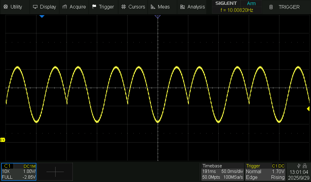
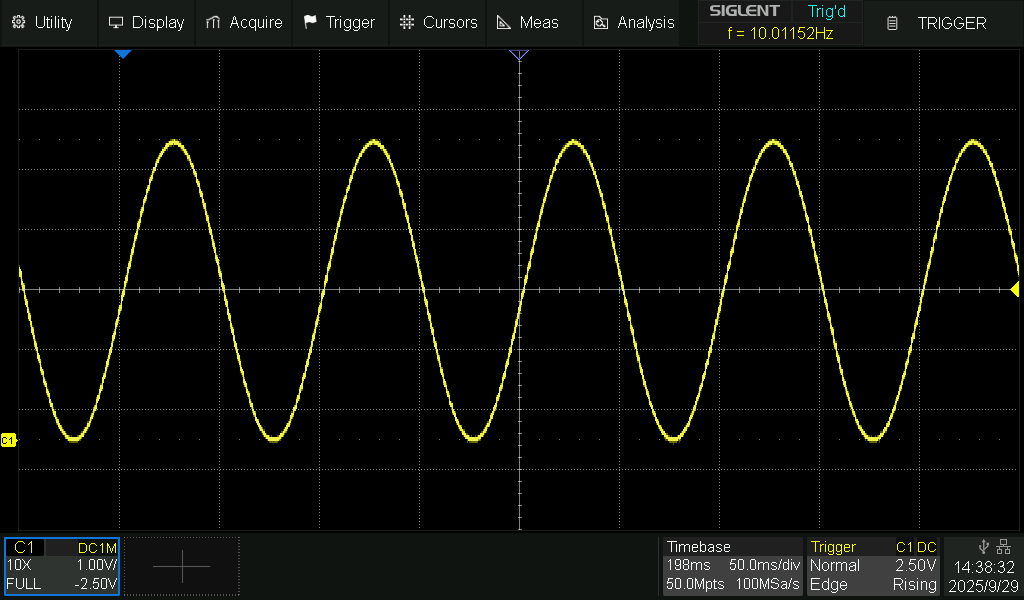
I just fixed the look up table to go though one cycle instead of 1.5 cycles.

Code
/*
 * High-Frequency PWM Waveform Generator with RC Filter
 *
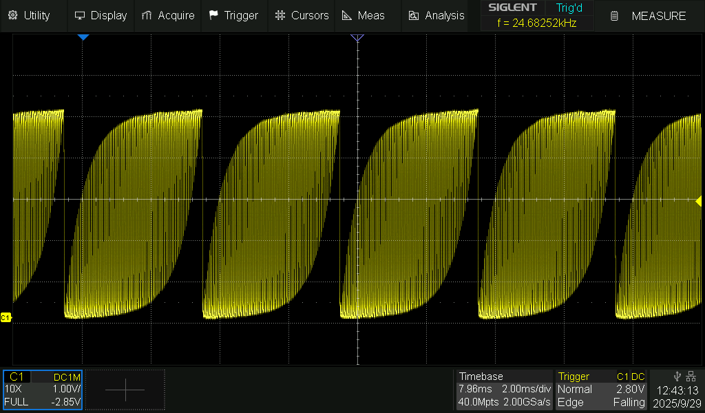
 * This sketch generates one of three waveforms (square, sawtooth, sine)
 * by updating the PWM duty cycle on pin 9 at a rate determined by the desired
 * waveform frequency and the number of samples per period.
 *
 * The PWM output is filtered through an external RC low-pass filter 
 * (e.g., a 470 Ω resistor in series with a 10 nF capacitor to ground) 
 * to produce a smooth analog voltage.
 *
 * User inputs (via Serial Monitor):
 *   - Waveform type: 1 = square, 2 = sawtooth, 3 = sine.
 *   - Desired waveform frequency in Hz.
 *
 * NOTE on Serial Input:
 * A custom function getInput() is used to prompt for and retrieve a complete,
 * non-empty line from the Serial Monitor without inserting delays. This avoids
 * the problem of leftover end-of-line characters (EOL's) being interpreted as
 * empty input.
 *
 * For more information on the Serial API, see:
 *   - Serial.begin(): https://docs.arduino.cc/reference/en/language/functions/communication/serial/begin/
 *   - Serial.available(): https://docs.arduino.cc/reference/en/language/functions/communication/serial/available/
 *   - Serial.readStringUntil(): https://docs.arduino.cc/reference/en/language/functions/communication/serial/readstringuntil/
 *
 * ++u/ripred3 – Feb 3, 2025
 *
 */

#include <Arduino.h>
#include <avr/interrupt.h>
#include <avr/pgmspace.h>

#define NUM_SAMPLES 64      // Number of samples per waveform period
#define PWM_PIN 9           // PWM output pin (Timer1 output)

// ---------- Global Variables ----------
volatile uint8_t waveform_type = 0;   // 1: square, 2: sawtooth, 3: sine
volatile uint16_t sample_index = 0;   // Current index for waveform sample progression
volatile uint8_t saw_value = 0;       // Sawtooth waveform current value

// ---------- Sine Wave Lookup Table (8-bit values: 0-255) ----------
const uint8_t sine_table[NUM_SAMPLES] PROGMEM = {
  128, 140, 152, 164, 176, 187, 198, 208,
  217, 226, 233, 240, 245, 249, 252, 254, 
  255, 254, 252, 249, 245, 240, 233, 226, 
  217, 208, 198, 187, 176, 164, 152, 140, 
  128, 115, 103,  91,  79,  68,  57,  47, 
  38,   29,  22,  15,  10,   6,   3,   1,
  1,     1,   3,   6,  10,  15,  22,  29,
  38,   47,  57,  68,  79,  91, 103, 115   
};

// ---------- Timer2 Prescaler Options ----------
struct PrescalerOption {
  uint16_t prescaler;
  uint8_t cs_bits;  // Clock select bits for Timer2 (CS22:0)
};

PrescalerOption options[] = {
  {1,    (1 << CS20)},
  {8,    (1 << CS21)},
  {32,   (1 << CS21) | (1 << CS20)},
  {64,   (1 << CS22)},
  {128,  (1 << CS22) | (1 << CS20)},
  {256,  (1 << CS22) | (1 << CS21)},
  {1024, (1 << CS22) | (1 << CS21) | (1 << CS20)}
};
#define NUM_OPTIONS (sizeof(options) / sizeof(options[0]))

// ---------- Timer2 ISR: Updates PWM Duty Cycle ----------
ISR(TIMER2_COMPA_vect) {
  uint8_t output_val = 0;
  
  switch (waveform_type) {
    case 1: // Square wave: output 255 for first half of samples, then 0.
      output_val = (sample_index < (NUM_SAMPLES / 2)) ? 255 : 0;
      break;
      
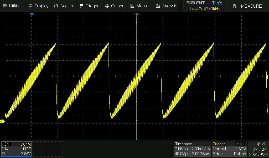
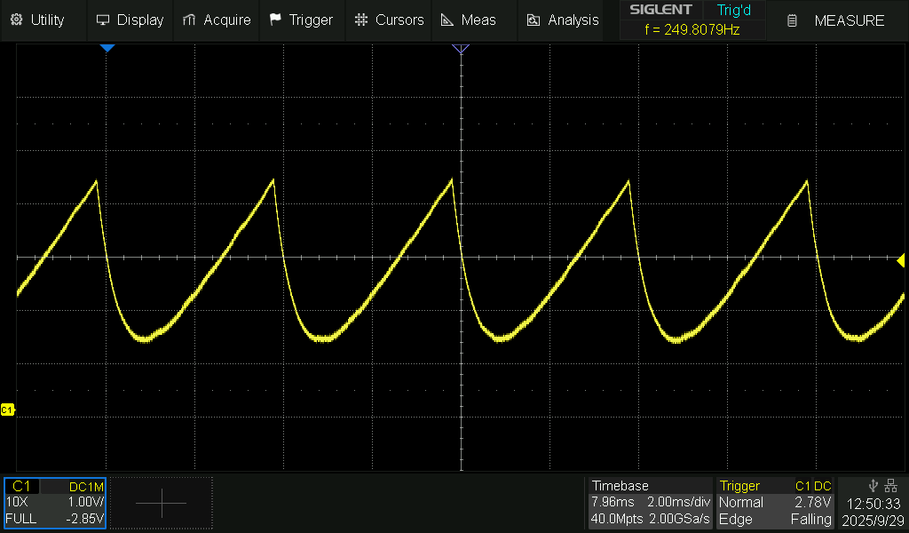
    case 2: // Sawtooth wave: continuously increment value.
      output_val = saw_value;
      saw_value++;  // 8-bit arithmetic wraps from 255 back to 0.
      break;
      
    case 3: // Sine wave: retrieve value from lookup table.
      output_val = pgm_read_byte(&(sine_table[sample_index]));
      break;
      
    default:
      output_val = 0;
      break;
  }
  
  sample_index++;
  if (sample_index >= NUM_SAMPLES) {
    sample_index = 0;
  }
  
  // Update Timer1's PWM duty cycle by writing to OCR1A.
  OCR1A = output_val;
}

// ---------- Function: getInput -----------------
// Prompts the user and waits (busy-waiting) for a non-empty line from the Serial Monitor.
// Uses Serial.available() and Serial.readStringUntil() without adding delay() calls.
// For Serial API details, see:
//   - Serial.available(): https://docs.arduino.cc/reference/en/language/functions/communication/serial/available/
//   - Serial.readStringUntil(): https://docs.arduino.cc/reference/en/language/functions/communication/serial/readstringuntil/
String getInput(const char* prompt) {
  Serial.println(prompt);
  String input = "";
  // Busy-wait until a non-empty line is received.
  while (input.length() == 0) {
    if (Serial.available() > 0) {
      input = Serial.readStringUntil('\n');
      input.trim(); // Remove any whitespace or EOL characters.
    }
  }
  return input;
}

// ---------- Setup Timer2 for Waveform Updates ----------
void setup_timer2(uint32_t sample_rate) {
  uint8_t chosen_cs = 0;
  uint16_t chosen_ocr = 0;
  
  // Determine a prescaler option yielding OCR2A <= 255.
  for (uint8_t i = 0; i < NUM_OPTIONS; i++) {
    uint32_t ocr = (F_CPU / (options[i].prescaler * sample_rate)) - 1;
    if (ocr <= 255) {
      chosen_cs = options[i].cs_bits;
      chosen_ocr = ocr;
      break;
    }
  }
  
  // If no valid prescaler was found, use the maximum prescaler.
  if (chosen_cs == 0) {
    chosen_cs = options[NUM_OPTIONS - 1].cs_bits;
    chosen_ocr = 255;
  }
  
  cli();  // Disable interrupts during Timer2 configuration.
  
  TCCR2A = 0;
  TCCR2B = 0;
  TCNT2  = 0;
  
  TCCR2A |= (1 << WGM21);  // Set Timer2 to CTC mode.
  OCR2A = chosen_ocr;
  TCCR2B |= chosen_cs;
  TIMSK2 |= (1 << OCIE2A); // Enable Timer2 Compare Match interrupt.
  
  sei();  // Re-enable interrupts.
}

// ---------- Setup Timer1 for PWM Output on Pin 9 ----------
void setup_timer1_pwm() {
  pinMode(PWM_PIN, OUTPUT);
  
  cli(); // Disable interrupts during Timer1 configuration.
  
  TCCR1A = 0;
  TCCR1B = 0;
  TCNT1  = 0;
  
  // Configure Timer1 for 8-bit Fast PWM on channel A (pin 9) in non-inverting mode.
  TCCR1A |= (1 << WGM10) | (1 << COM1A1);
  TCCR1B |= (1 << CS10);  // No prescaling: PWM frequency ≈ 16MHz/256 ≈ 62.5 kHz.
  
  sei(); // Re-enable interrupts.
}

// ---------- Setup Function ----------
void setup() {
  Serial.begin(115200);  // Preferred baud rate.
  while (!Serial) { }     // Wait for the Serial Monitor connection.
  
  Serial.println(F("High-Frequency PWM Waveform Generator"));
  Serial.println(F("======================================"));
  
  // --- Get Waveform Type ---
  String typeString = getInput("Enter waveform type (1 = square, 2 = sawtooth, 3 = sine):");
  waveform_type = typeString.toInt();
  Serial.print(F("Waveform type: "));
  Serial.println(waveform_type);
  
  // --- Get Desired Waveform Frequency ---
  String freqString = getInput("Enter desired waveform frequency in Hz (e.g., 100):");
  uint32_t waveform_freq = freqString.toInt();
  Serial.print(F("Waveform frequency: "));
  Serial.print(waveform_freq);
  Serial.println(F(" Hz"));
  
  // Compute the sample rate as: waveform frequency * NUM_SAMPLES.
  uint32_t sample_rate = waveform_freq * NUM_SAMPLES;
  Serial.print(F("Computed sample rate: "));
  Serial.print(sample_rate);
  Serial.println(F(" Hz"));
  
  // Initialize PWM on Timer1.
  setup_timer1_pwm();
  
  // Initialize Timer2 to update the PWM duty cycle.
  setup_timer2(sample_rate);
  
  Serial.println(F("Setup complete."));
  Serial.println(F("Remember to apply the RC low-pass filter (e.g., 470 Ω resistor + 10 nF capacitor) to PWM output on pin 9."));
}

// ---------- Main Loop ----------
void loop() {
  // No processing is needed here as waveform generation is handled in the Timer2 ISR.
  // The loop remains empty to allow uninterrupted timer interrupts.
}

What cut-off frequency would that give?

What will the filter do if the cut-off frequency is above the PWM frequency?

Place 20x 10K in parallel. That will give you 500R.

Then place an order for a selection of resistor values!

That sounds much more like it! :heart:

Place 20x 10K in parallel. That will give you 500R

Done, works perfectly!

Thanks people!