I am trying to get my Lcd Shield up and running. I was having problems trying to install the LCD4Bit_mod and later read a post that suggested I don't need that file to run the Lcd Shield.
So I decided to try and use LiquidCrystal instead. I changed the Lcd pins from (12, 11, 5, 4, 3, 2) to (14, 13, 12, 11, 6, 5 - the pins used on the shield) but it's not that straight forward as I found. I had to comment out these 4 lines of code below to get the code to verify, otherwise I got all kinds of errors;
Does anyone know of any sample code for the Lcd Shield that uses the LiquidCrystal.h include instead of the LCD4Bit_mod.h include? Or if anyone could offer any advice on what to do.
Any help would be greatly appreciated.
What does it say on the board itself ? DFROBOT ? or SaintSmart ? or Adafruit ? or did you buy it on Ebay ?
Is it the one with:
pin 4 = DB4
pin 5 = DB5
pin 6 = DB6
pin 7 = DB7
pin 8 = RS
pin 9 = Enable
pin 10 = Backlight ?
I want to be sure which LCD Shield you have. Can you make a photo of both sides ?
You use the pins 14, 13, 12, 11, 6, 5. Where did you find those pins ? Pin 14 doesn't exist on most Arduino boards. Which Arduino board do you have ?
If you use the example at that page, and select your own pins, it would be something like this:
// include the library code:
#include <LiquidCrystal.h>

// initialize the library with the numbers of the interface pins
LiquidCrystal lcd(8, 9, 4, 5, 6, 7);

void setup() {
  // set up the LCD's number of columns and rows:
  lcd.begin(16, 2);
  // Print a message to the LCD.
  lcd.print("hello, world!");
}

void loop() {
  // set the cursor to column 0, line 1
  // (note: line 1 is the second row, since counting begins with 0):
  lcd.setCursor(0, 1);
  // print the number of seconds since reset:
  lcd.print(millis()/1000);
}
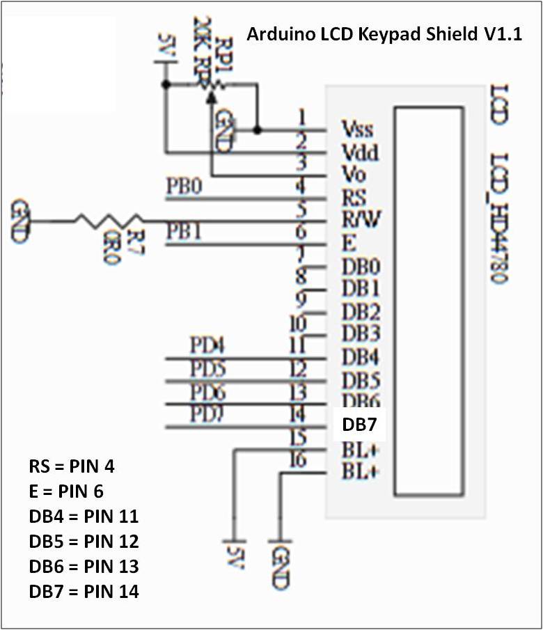
As you can see from the picture of the Lcd Shield pinout, I made a mistake - it should be pin 4 and not pin 5 as I posted in my first post. Thanks for the links - there are lots of Lcd code examples there.
Thank you for the photos. I think "Deek Robot" is a clone of "DFRobot".
The "PIN 11" and so in the drawing is the pin number of the LCD shield. Not the Arduino pin number !
According to that drawing:
DB4 = Arduino pin 4
DB5 = Arduino pin 5
DB6 = Arduino pin 6
DB7 = Arduino pin 7 (although I read this one clearly)
And if I look at the photo of the back side, and follow the copper traces, I think that are the pins.
I can't figure out 'E' and 'RS'. They could be connected to Arduino pin 0 and 1 but also to 8 or 9, or 10, or 11.
Do you have a multimeter ? Can you measure to which Arduino pins the 'E' and 'RS' of the LCD are connected ?
You could try RS = 8 and E = 9. Did you try the example in the previous post ?
LiquidCrystal lcd(8, 9, 4, 5, 6, 7);
With the example running you have to adjust the variable resistor, until the characters become visible.
I think Erdin's right. That shield looks exactly like the DFRobotics DFR0009, which indeed uses those values. There's sample code on that linked page...
Hello Erdin & Jimbo,
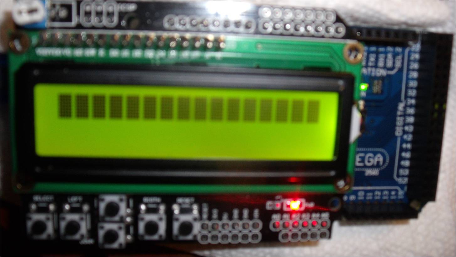
No success yet but I haven't given up. I did as you suggested Erdin and used my multimeter to determine the pin numbers which I have in the code below. The code below compiles but only shows the the top line with black boxes as the attached picture shows. I did try adjusting the variable resistor but no cigar. I must be missing something in the code. I also tried running the code you sent me to try and I also changed the pin numbers and got the same results. I will keep plugging away trying to figure out what's wrong and in the meantime if you or anyone else can think of something else to try, it will be much appreciated.
Thanks
jessey
#include <LiquidCrystal.h>
LiquidCrystal lcd(10, 9, 7, 6, 5, 4);

// define some values used by the panel and buttons
int lcd_key     = 0;
int adc_key_in  = 0;
#define btnRIGHT  0
#define btnUP     1
#define btnDOWN   2
#define btnLEFT   3
#define btnSELECT 4
#define btnNONE   5

// read the buttons
int read_LCD_buttons()
{
 adc_key_in = analogRead(0);      // read the value from the sensor
 // my buttons when read are centered at these valies: 0, 144, 329, 504, 741
 // we add approx 50 to those values and check to see if we are close
 if (adc_key_in > 1000) return btnNONE; // We make this the 1st option for speed reasons since it will be the most likely result
 if (adc_key_in < 50)   return btnRIGHT;
 if (adc_key_in < 195)  return btnUP;
 if (adc_key_in < 380)  return btnDOWN;
 if (adc_key_in < 555)  return btnLEFT;
 if (adc_key_in < 790)  return btnSELECT;
 return btnNONE;  // when all others fail, return this...
}

void setup()
{
 lcd.begin(16, 2);              // start the library
 lcd.setCursor(0,0);
 lcd.print("Push the buttons"); // print a simple message
}

void loop()
{
 lcd.setCursor(9,1);            // move cursor to second line "1" and 9 spaces over
 lcd.print(millis()/1000);      // display seconds elapsed since power-up


 lcd.setCursor(0,1);            // move to the begining of the second line
 lcd_key = read_LCD_buttons();  // read the buttons

 switch (lcd_key)               // depending on which button was pushed, we perform an action
 {
   case btnRIGHT:
     {
     lcd.print("RIGHT ");
     break;
     }
   case btnLEFT:
     {
     lcd.print("LEFT   ");
     break;
     }
   case btnUP:
     {
     lcd.print("UP    ");
     break;
     }
   case btnDOWN:
     {
     lcd.print("DOWN  ");
     break;
     }
   case btnSELECT:
     {
     lcd.print("SELECT");
     break;
     }
     case btnNONE:
     {
     lcd.print("NONE  ");
     break;
     }
 }

}