Not working
I have try to connect it directtly to the USB-Serial
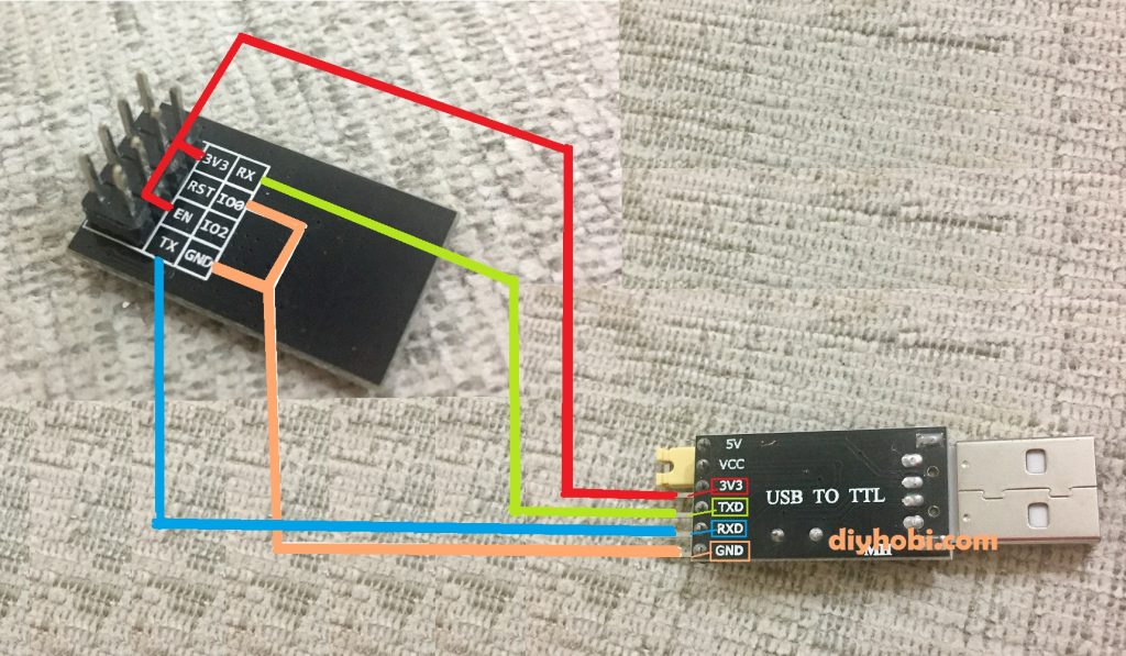
Flash ESP-01 using USB to TTL CH340G Converter Module Adapter
did the same connection
GND - GND,IOO
VCC (3.3V) - VCC,En
Rx - Tx
Tx-Rx
Arduino: 1.8.13 (Windows 7), Board: "Generic ESP8266 Module, 80 MHz, Flash, Legacy (new can return nullptr), All SSL ciphers (most compatible), no dtr (aka ck), 26 MHz, 40MHz, DOUT (compatible), 1MB (FS:64KB OTA:~470KB), 2, nonos-sdk 2.2.1+100 (190703), v2 Lower Memory, Disabled, None, Only Sketch, 115200"

Sketch uses 257316 bytes (26%) of program storage space. Maximum is 958448 bytes.

Global variables use 26816 bytes (32%) of dynamic memory, leaving 55104 bytes for local variables. Maximum is 81920 bytes.

C:\Users\David\AppData\Local\Arduino15\packages\esp8266\tools\python3\3.7.2-post1/python3 C:\Users\David\AppData\Local\Arduino15\packages\esp8266\hardware\esp8266\2.7.4/tools/upload.py --chip esp8266 --port COM19 --baud 115200 --before no_reset --after soft_reset write_flash 0x0 C:\Users\David\AppData\Local\Temp\arduino_build_23603/Blink.ino.bin

esptool.py v2.8

Serial port COM19

Connecting........_____....._____....._____....._____....._____....._____....._____

Traceback (most recent call last):

  File "C:\Users\David\AppData\Local\Arduino15\packages\esp8266\hardware\esp8266\2.7.4/tools/upload.py", line 65, in <module>

    esptool.main(cmdline)

  File "C:/Users/David/AppData/Local/Arduino15/packages/esp8266/hardware/esp8266/2.7.4/tools/esptool\esptool.py", line 2890, in main

    esp.connect(args.before)

  File "C:/Users/David/AppData/Local/Arduino15/packages/esp8266/hardware/esp8266/2.7.4/tools/esptool\esptool.py", line 483, in connect

    raise FatalError('Failed to connect to %s: %s' % (self.CHIP_NAME, last_error))

esptool.FatalError: Failed to connect to ESP8266: Timed out waiting for packet header

esptool.FatalError: Failed to connect to ESP8266: Timed out waiting for packet header
did I miss something in the connections?
also I have found this link
https://learn.adafruit.com/esp8266-temperature-slash-humidity-webserver/ide-setup
and it said to disconnect the D0 from gnd after boot
but when I look at the IDE-Setting
https://learn.adafruit.com/esp8266-temperature-slash-humidity-webserver/ide-setup
you can see it said to use "esptool " ad the progrmamer
and
I want to connect the ESP-01 to Arduino in order to read data from him