Hi, this is my first post, sorry if i miss something and thanks for been there!
My question is: i have a battery powered arduino, and i want it to be switched off (saving battery energy) until someone clicks a push button like this : https://images.app.goo.gl/MpD4ZWjwrTYeV4BX8
After the arduino ends doing what it should do, i want the arduino to be powered off again until someone pushes the button back again and so on....
Is that possible? I'm struggling with mossfets but not sure if that is the solution.
Thanks!
What you need is a switch between the Arduino and the battery, an old style on/off power switch.
Be happy, there's no code involved!
I suspect Reply #1 does not capture what the OP is hoping to achieve.
You can put an Atmega 328 microprocessor into a SLEEP mode to save energy and it can be woken up by an interrupt caused by a switch being pressed.
Have a look at Nick Gammon's power saving tutorial
...R
The OP described a power switch. Sleep mode uses low power, a cutoff switch makes that "uses NO power".
Hi, thanks, this gaves me a clueto search for: CUTTOFF SWITCH. Thanks to that, i found this great tutorial to do exactly what i'm looking for: Arduino Tutorial: Arduino Auto Power off. Make Arduino power off itself! - YouTube
Last question, sorry but i'm new to these mossfets, can i use a MOSFET IRF520 instead of the single mossfet and resistors shown o the video? If so, how will be the scheme?
Many thanks for the quick and multiple responses to all
Sorry, I don't have the bandwidth to watch videos.
The resistor between Arduino pin and MOSFET is to prevent the FET from pulling too much current from the pin in the very short time it takes to activate the FET. It's there to protect the Arduino.
MOSFET = metal oxide semiconductor field effect transistor. No moss involved.
Sorry, this is the schematic:
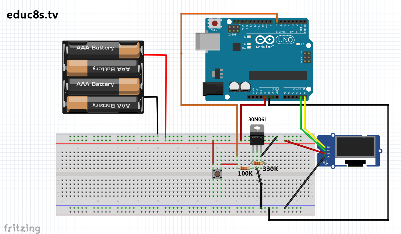
As said, can i use a IRF520 instead?
Thanks again
IRF520 is not a logic level MOSFET and doesn't switch on properly with 5V at the gate; the IRL520 would work well with an Arduino.
Check the data sheets for on resistances at VGS = 4.5V or lower. If that's not given, it's not good for switching with an Arduino.
Rcup:
Sorry, this is the schematic:
That's not a schematic, it's a Fritzing image. Unreadable at best, usually misleading and lacking information.
That switch is not wired well. You can place it between pin and GND, do away with that 100k resistor (that's a pretty big value for reliable pull-down anyway), and instead use the built-in pullup resistor.
Attached is a schematic posted in another thread on this general subject. It's a bit different in that a single GPIO pin is used to read the state of the pushbutton and to keep the power on - it's configured as INPUT-PULLUP. If memory serves, this is by Ian.M.

There are type P MOSFETs and type N MOSFETs that don't work the same, you can't swap them in general (some exceptions possible and still one will be better). The hardware people here know more than I do about this.
I got IRLZ44N's pretty cheap a while back and may never need to buy MOSFETs again. Maybe.