Hello,
i can't figure out how to wire simple switch (mosfet, transistor) while using load with very low consumption (1mA and less). I read alot of posts here and tryed alot of variants. I have no problem to turn load on, but turn it off. Somewhere on forum i read it could be because mosfet have some D/S leakage so its better use regular PNP transistor, but since im using 3V3 arduino which driving 12V device (with 1mA consumption), its dont working, since im unable to put gate on 12V to turn it off. Tryed also with NPN transistor but with same result as with N-mosfet. I can try buy some very low leakage mosfet, but im not sure, if there is chance it should help.
Easy solution to get it work is just add 1k resistor parallel to load which add like 10mA. Then its working well with N-mosfet. But i dont want to do it this way since there will be multiple devices connected and in total it should be like 1Amp of wasted energy... is there some clever/simple solution for this ?
Can you provide a circuit of your project, how are you connecting the circuit to power supplies and how are you turning the gate on and off?
Have you got a 10K between the gate circuit and the source?
Have you got the load power supply and the controller supply gnds connected together?
to TomGeorge:
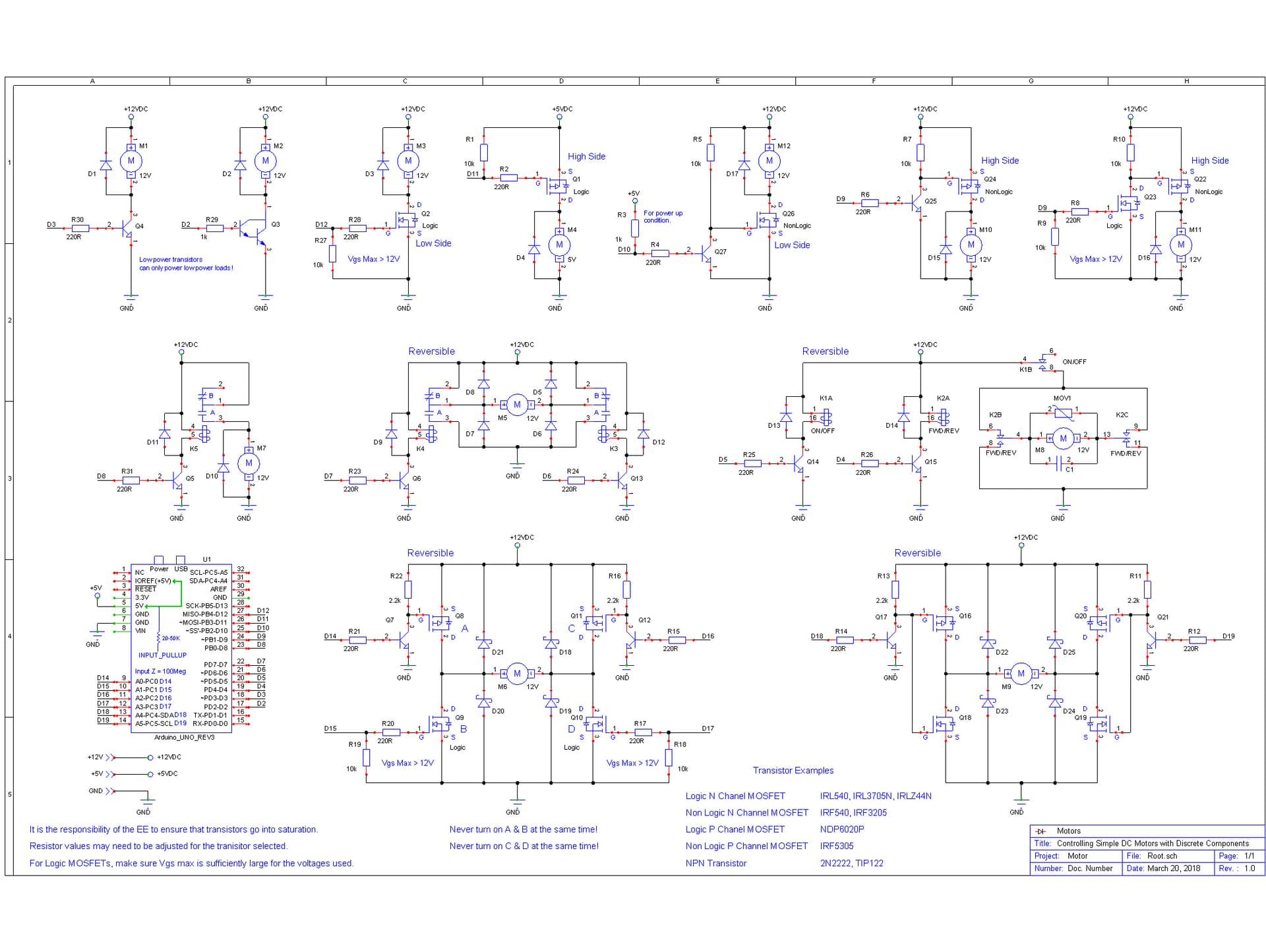
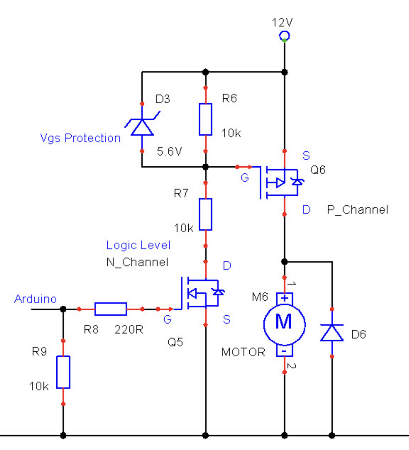
i tryed almost all of them, my question was more general meaning then pointing on one, but attaching the last one because someone in here pointed that should work fine. its number 6 adding in attachement.
to 6v6gt and Grumpy_Mike:
using BC547 as NPN, BC557 as PNP, BS170 as N-Mosfet and BS250 as P-Mosfet
schematics i attached was just an example which i found here on forum form someone like you Grumpy_Mike (meaning from someone who helping others replying to all this questions again and again - problem with switching is here very common and its also why i tryed to ask more general then discus on specific scheme because they are all here, and as i said i read and google alot before ask).
Thanx all for help
i tryed again scheme number 6. with proper R7 (i had 470ohms from some another example presented on this forum before). 10kOhm fixed it and now its running good with BC547 as NPN and BS250 as P-MOS
special thanx to 6v6gt - your link to that example on sparkfun reset my mind to made another try