Tutorial on setting up and installing the FT232 driver

Required parts
1: ftdi232
2: Mini USB cable
3: microcontroller
4: 100nF capacitor
In this tutorial, we will teach you how to set up and install the FT232 driver. This USB to TTL converter module with the FT232 chip is one of the most widely used modules used to program microcontrollers and some modules that have TTL communication.
First download the file below.
FT232R-USB-UART-Driver (1).zip (270.2 KB)
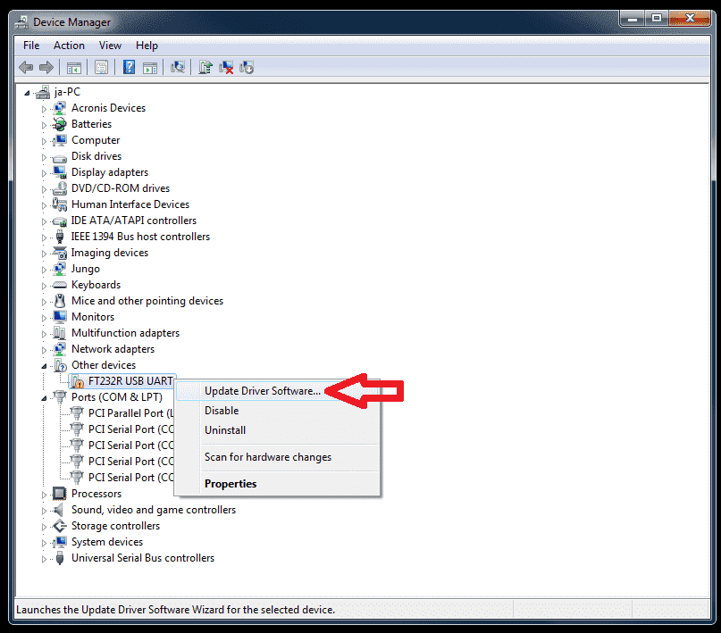
Then open Device Manager and connect the USB to TTL converter to the system. If the system does not recognize the converter, a warning sign will appear next to the converter name, as shown in the image. Right-click on it and click Update driver.
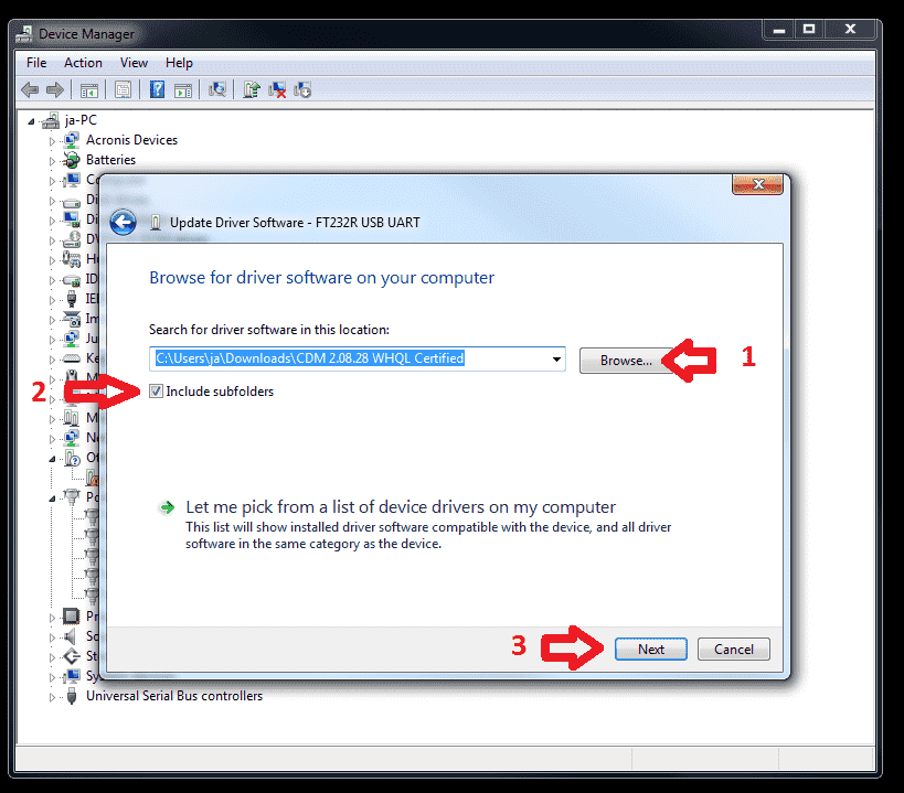
At this stage, first click on Browse my computer for drivers, then go to the path of the driver you downloaded as shown in the image below. If your system is 64-bit, enter the x64 path address. If your system is 32-bit, enter the x86 address and click Next.
At this point, wait for the driver to be installed.

And in the last step, after installing the driver, click Close.

Learning how to connect FT232 to microcontrollers
You can use this module to start up micros and modules that have TTL communication. Connect the FT232 module to the desired micro and module according to the schematic below and then you can use it.

According to the picture, TX is converted to RX of the micro, RX is converted to TX of the micro, and the DTR pin is connected to the RESET pin of the micro with a 100nF capacitor. Then you can do whatever you want.
Preparing the Arduino IDE software
1: Open File > Preferences.
2: In the Additional Board Manager URLs section, add the following link:
https://mcudude.github.io/MightyCore/package_MCUdude_MightyCore_index.json
Arduino IDE settings
From the Tools menu, select the following options:
1: Board → "The microcontroller you have connected to the ft232"
2: Clock → "External 16 MHz" (if you are using an external crystal)
3: Programmer → "Arduino as ISP"
4: Port → The port to which the FT232 is connected
5: Bootloader → "Yes" (if bootloader is required)
Upload sample code
#define LED 5

void setup() {
  pinMode(LED, OUTPUT);
}

void loop() {
  digitalWrite(LED, HIGH);
  delay(1000);
  digitalWrite(LED, LOW);
  delay(1000);
}
If you get an error, close the Arduino and reopen it.
If you had this error while uploading:
Sketch uses 344 bytes (1%) of program storage space. Maximum is 32384 bytes.
Global variables use 9 bytes (0%) of dynamic memory, leaving 2039 bytes for local variables. Maximum is 2048 bytes.
Warning: attempt 1 of 10: not in sync
Warning: attempt 2 of 10: not in sync
Warning: attempt 3 of 10: not in sync
Warning: attempt 4 of 10: not in sync
Warning: attempt 5 of 10: not in sync
Warning: attempt 6 of 10: not in sync
Warning: attempt 7 of 10: not in sync
Warning: attempt 8 of 10: not in sync
Warning: attempt 9 of 10: not in sync
Warning: attempt 10 of 10: not in sync
Warning: programmer is not responding; try -x strict and/or vary -x delay=100
Error: unable to open port COM6 for programmer urclock
Failed uploading: uploading error: exit status 1
Checking the connections between the FT232RL and the microcontroller
The "not in sync" and "programmer is not responding" errors occur when the microcontroller and programmer (such as the FT232RL) cannot communicate properly.
1: Make sure you have done the wiring correctly.
2: Important: The RESET pin must be connected to DTR via a 100nF capacitor. Otherwise, communication will not be established.
We hope that the tutorial on setting up and installing the FT232 driver was useful to you.