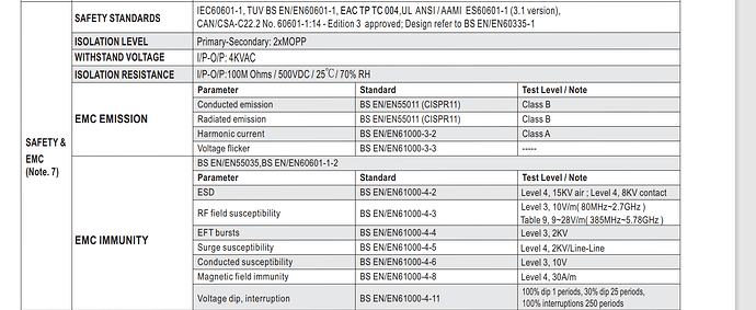
This is hard JohnRob. Thanks for your great comments and explanations. I actually bought Power supply that has 60601-4-4 feature. In its datasheet it says this power supply complient with 60601-4-4 too. I get confused after these mentions.
Yes it is. But it still can be done.
I have the right to try. If it is as you mentioned, we need to change the design. But I'm thinking of putting an aluminum shield to see if that's the problem. If the problem is solved with it, I will follow a path accordingly.
Do I need to make a connection between this aluminum shield and the power supply? Or is it enough to just connect the aluminum shield to ground and place it near the power supply?
But I didn't exactly tell you what the real problem was. During the test while the device is running, the LCD screen turns blue after 10-15 minutes. So actually there is noise on the screen side.
My last design which was subjected to a similar test for automotive, had the shield grounded.
From the little I know about your product I would connect the shield to the circuit ground closest to the input as possible. Note the shield could be copper tape (easy to solder to) or any of the commercial screen type shields.
As for the LCD turning blue after 10 - 15 minutes. I wasn't aware the test was that long.
Typically EMC testing shows failures immediately as the signals are compromised. Something that occurs after 10 minutes or so is likely heat being generated by the test currents. Seems unlikely for this test but is a possibility.
This is hard JohnRob
Yes. I was fortunate to work at a company that could do their own testing. It afforded me the ability to learn the effects of the test and how they enter and leave a test article. One also needs to have a "knack" for RF.
For the automotive version of this test (which was much more aggressive than your test requirement) I was able to be successful by having a (relatively) large ground plane on the board near the input power supply.
This device is medical device. I was the responsible for only coding side but our electronic engineer left the job and currently I am the one who needs to go with these tests. Our device don't have any ground because we classified it as class II. The entire enclosure consists of plastic and there is no ground line.
The device passed for Radiated emissions side but this device fails with the immunity side.
I wasn't aware the test was that long.
This device doesn't have ground thats why it needs to go through this EFT test at least 30 minute according to standarts.
It actually worked for about 1 minute before working for 10-15 minutes and then the push buttons worked randomly. To solve this problem, I increased the button reading time and increased the test to 10-15 minutes. But as I said, the current problem is more like noise than software. That's my entire problem right now. I plan to try one more this week. Since I haven't worked much on the electronic side, my knowledge is not that good.
In this attempt, I will try adding a filter to the SPI line, adding a diode, and filters installed in the mains section of Würth Elektronik.
Thanks for your helps.
Then you MUST know in detail what that test consists of. The frequencies and the type of signal that caused the failure. There may be many type of test signal used, but any fix will depend on the source of the signal.. Also, the location of the signal source on the product will point to the part of the circuit needing fixing.
First stock up on capacitors that can be added to the circuit. You may need some ferrite beads to act as RF chokes on any leaded components. SMD components are much harder to deal with.
Any problem with solder joints are also suspect as they can act as diodes and generate spurious signals when least suspected.
The ground you need the connect the shield to is the powersupply negative to the circuit.
The "noise" is coming in both them mains, on both the line and neutral. It passes through your AC to DC conversion and goes through your circuitry, then passes to ground (the test bench) through whatever clad on the board (or maybe the LCD) and gets capacitively coupled to the test bench.
The goal is to provide this current a path to ground that doesn't effect the circuitry.
So if you have a 0.1µf cap from the +V to Circuit ground, and a path from the circuit ground to your shield, the test signal will/should pass from the V+ and ground to the shield to ground. Bypassing any of the circuitry. Look closely at my post #21.
Other thoughts:
-
Button issues can be reduced by increasing the pullup current (i.e. lower resister).
-
Assuming nothing failed (i.e. did not work after the test) the only though I have on the LCD is some thermal effect. However that would be a stretch for the power and path you described.
-
I don't know the logistics of your testing, we usually brought multiple units for testing, each with different configurations we felt could pass the test. If on failed we could quickly switch to another.
-
Another thing that has not been mentioned, the board layout. For medical I would assume there is a high degree of isolation between the device and the mains power. If this isn't the case, the problem could be more difficult to solve as you will less control of the path the test signal takes.
This topic was automatically closed 180 days after the last reply. New replies are no longer allowed.
