I have a circuit to control a Mercedes PWM fan using the Arduino Nano 33 BLE. Its been running fine for about 3 years now with out any sort of transient circuit protection. At recommendations from many on these forums, I decided to add transient voltage circuit protection. So I think I added it and the board still works functionally. But how can I tell if my transient suppression is good and will do the job. The circuits I added for transient protection consist of a TSV diode model TP6KE18A and shown as ICTE5 in the schematic and a standard diode model BAW27 shown as 1N4004 in the schematic. Yes I haven't figured out how to change the labels yet when using another footprint in Eagle Cad.
See attached data sheets. Two circuits are protected using this circuit. The first circuit is labeled C30 which is automotive battery power and C15 which is power from the ignition key on. C30 runs the Arduino including in sleep mode and is therefore powered at all times. The Arduino Nano 33 BLE will handle up to 21V but the goal for this circuit is to clip any transients above 18V.
So two questions. How does my transient circuit protection look and how can I test this to verify it is adequate?
Thanks for the for the reply. I would think shorting the two wires would just reduce the voltage to zero. Or will there be a high frequency spike. I don't have a fan at the moment to try this on the bench and wiring it to the car is difficult. Would this work if I replaced everything after the diodes with just a big maybe 5W 10Ω resistor going to ground. Could I monitor this on an 8 bit digital scope?
Transient testing could be a lot of things. A motor suddenly disconnected from power etc.
However in my experience designing automotive modules you should be able to design in protection the is 99+ % likely to pass transients. I quote the 99+% as a guess as none of my designs have failed the automotive transient requirements. The more difficult requirements are EMC and Bulk Current Injection.
That said I have some suggestions;
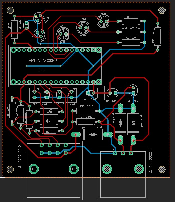
You should have more of a ground plane on your board. Especially at the grounds of the connector.
C4 and C5 (the 0.1µf input caps) needs to be right at the input pins. As close as possible.
D3 and D4 are superfluous and do nothing but take space.
You should put as much resistance in series with J2-3 and at least a couple of k ohms stolen from R1 in series with J2-2
Then comes your Transient diodes D1 and D2.
Up to here all these components need to be close to J2.
There is no protection for J1. You will need the same as for J2 except for the 10µf.
To be honest you probably cannot fully qualify it. The OEMs (Original Equipment Manufacturers) test and qualify every part, assembly, assembly etc. This takes about two years. The testing equipment will run into the millions. There are a bunch of standards called AEC-100. There is a whole series. Here is a link to get you started: https://media.monolithicpower.com/mps_cms_document/w/e/Webinar_-_Fundamentals_of_AEC-Q100-6Nov2018.pdf You are one of the lucky ones yours worked. There is a big difference between doing it for yourself and for an Automotive OEM. You only have do do what you want but stay from the safety critical devices, they can give you a lot of grief depending on your locations and regulations. Also you need to consider what happens if it fails and how it will fail.
I first saw circuit transient protection being demonstrated was a show in Portland, Oregon, perhaps 1970. The transients and noise was introduced by using a battery powered buzzer using a make-break solenoid with one side of it's power connected to the circuit. It was also held near the circuit. A scope on the circuit clearly showed the noise and voltage transients. When the suppression components were added the noise signal pretty much went away.
You can try something similar with your circuit.
I have been debating about the ground plane. The board I currently have in the car has a full ground plane. I have heard that ground planes interfere with the Blue Tooth. I do use the blue tooth feature to report temperatures and fan speeds to my cell phone. I really haven't had any problems except sometimes it is hard to connect. But once connected it works well. I believe I can figure out a way of masking the ground plane in the area of the Arduino.
I believe I can move C4 and C5 up close but can I leave C6 and C7 further away? Also, can i move C1, C2, C3 further away to get more room? Also can C4 be placed on the other side of the voltage divider resistors C14 and C15?
D3 and D4 will be removed. I forgot why I put them in.
I'm not following you with step 4.
I can get the transient closer to J2
If I understand you correctly for step 6, I need another TVS diode on pin A4 of J1 and a 0.1µf cap? Should the 0.1µf cap be closer to the J1 connector or should it be close to the Q2 transistor?
I obviously cant fully qualify it. I am well aware of what goes on in qualification at least in Aerospace and I'm sure the same goes for automotive. But I can use best practices and hope for the best. One nice feature about the Mercedes fan, if it looses a PWM signal, the fan runs at 100%.
I don't understand where the buzzer comes in but I can give it a try with a scope and making and breaking the circuit. I will have to wait until I can get a fan to try something out on the bench.
The buzzer making and breaking the circuit powering is makes sparks at the points and they will introduce a vast quantity of noise pulses into your circuit when one of the buzzer power wires touches your circuit.
That is not a real test, put a dead battery in start the vehicle then disconnect and connect the battery a few tines, imitate a lose connection. Those current spikes will be well over 100 Amps. That is basically how we test a car. Schaffner makes a great test unit for this. Schaffner was bought out by Teseq. This is spelled out in the AEC specifications as load dump. Some of the US OEM specifications are even more stringent then these. Is this a one up or many? Here is one published environmental temperature chart. Remember many of the AEC tests are performed are many times at temperature.
Seems like a simple enough test to do. But it will take me a few months to get access to the car in storage. This is a one off application. As I have stated, I have been running it without any transient protection for about 3 years now. But I've never had a dead battery in that time and I have been keeping a spare with me for all that time, but never had to change it. My design point is grade 3 but I would like to get to grade 1or 2 so it can be put under the hood.
If you are putting a power device in your package you also need to calculate the heat it will rise above ambient. Grade 2 would be in the perimeter of the engine compartment without power dissipating devices. General grade 1 would be used and grade 0 if mounted on the engine. Check the vibration specifications they will impact your design.
This is not how I recall load dump. We've tested for US, EU and Japan automakers. Testing is never performed in a vehicle and it would be difficult to start a vehicle with a dead battery.
The energy behind load dump is what is stored in the alternator magnetic circuit, released when a high current device is disconnected (things like rear window heater, cooling fan etc).
From my recollection the generated pulse is either 50V or 80V (depending on the OE). It decays over 100 ms or so and has a defined energy. I built one using large capacitors and resistors. I don't recall the circuit but I remember the larger capacitor was charged to the required voltage, then dumped into a smaller capacitor in parallel with a resistor. The device under test was connected to the smaller capacitor and resistor.
The short transient was 1500 volts (or so) for a very short duration.
Unfortunately the Nano 33 BLE is the limiting factor at the moment specs say it -40°C to 85°C. So until something more robust comes along I wont be putting it under the hood.
Sounds like a simple test where I put a motor or buzzer in parallel with the circuit and disconnect it might do a simple qualitative test. Question is will I need to be concerned with my scope seeing huge voltage spikes. I will need to run the test with and without the TSV diodes to see if anything is happening. At the moment all I have to go on is that the fan runs both with or without the diodes. But I would like to know I did something positive and see the diodes do there thing. Never mind even doing it on this particular circuit. Just a simple demonstration test of the TSV diodes. I assume I'm not going to get it tuned just right with my limited experience and equipment but I should be able to verify that I made the situation better. After all, I am tackling a problem that in 3 years has not reared its ugly head.
The specifications for the Japan automakers were easier, they put protection in the alternator, the US did not. Early automotive 80v was not uncommon and higher levels were sometimes measured. Check this link: protection - How do I protect against an automotive load dump? - Electrical Engineering Stack Exchange I also stated that was way to imitate it, I also mentioned there was appropriate test equipment which I used and is expensive. I also mentioned"There is a big difference between doing it for yourself and for an Automotive OEM"
Load dump is the disconnection of a heavy load while the battery is charging. It is actually an inductive kickback generally from the alternator. What happens is the load disconnects time passes (milliseconds is enough) the regulator detects the voltage is going up, backs down excitation for the alternator and brings its output back to normal. From when the battery disconnects until the regulator starts to correct for that the output of the alternator is dumped into the electrical system that does not have voltage limiting other then high voltage transients..
Haven't figured out the ground plan at this time but I will be working on it.
C4 and C5 have been moved to the input pins. In the case of C4, I moved it to the other side of the voltage divider. There should be < 2V at that point.
D3 and D4 have been removed
If I understand you correctly I don't need to be concerned with step 4.
Transient diodes have been moved as close to the connectors as possible.
I added a transient diode to J1. I also added a 0.1µf input cap near transistors.