hello experts,
I am working on a task
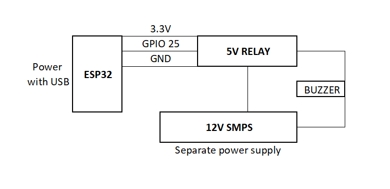
It includes ESP32, Max485, P10 displays, Buzzer (relay).
The Esp32 is powered through 5v 2amp adapter and ferrite bead as well as 103,104 caps are used before Vin pin.
The 5v relay module is powered directly by same adapter, but the trace is connected to Esp32 Vin pin.
I am using a power supply of 12v 5amp to Buzzer, which is triggering through 5v relay, controlled by Esp32 gpio32.
My issue is, when my relay is triggering the 12v buzzer, Esp32 started malfunctioning for a moment.
But, it is not happening on every trigger, it randomly occures and all cycle disturbes
I can not understanding, what is happening and why
My thinking is,
It may be voltage spikes
Need to use flyback diode in parallel
Need to use ferrite bead and 103, 104 caps near relay power supply
This sounds like it could be related to EMI, either conducted or radiated. While I can't confirm this is the problem without more information, I also can't rule it out. Most MOS logic circuits are fast and sensitive to edge transitions. Minimizing lead lengths (which act as antennas) to less than 10 inches (25 cm) is crucial, as longer leads can pick up frequencies up to about 750 MHz, not accounting for reflections and other effects.
Tips to Reduce EMI:
Keep Connections Short: Both transmitters and receivers are affected by antenna length—longer antennas have greater gain and can pick up more interference. Use the KISS principle: Keep It Short & Simple.
Avoid Parallel Lines: Ensure power and logic lines are not running parallel to each other to minimize crosstalk and interference.
Use a Zero-Crossing Solid-State Relay: This can be a simple and effective solution to reduce EMI, especially when dealing with AC loads.
Historical Context: This issue has been known since the early 1960s with TCTL (Transistor-Coupled Transistor Logic), later known as TTL (Transistor-Transistor Logic). It prompted the development of line drivers and other technologies to manage EMI.
For further reading on related topics, check out these resources:
Triac Principles and Circuits, Part 1: Learn about triacs, which are often used in switching applications and can be susceptible to EMI. Read Part 1
Triac Principles and Circuits, Part 2: This article continues exploring triac applications and EMI considerations. Read Part 2
Arduino Forum Discussion on Flashing LEDs: An example of EMI considerations in a practical Arduino project.
I am not expert, but i had used optocoupler and triac once, to handle 220v lamp switching. It was Moc3041 and BT136, with some resistors. Worked fantastic.
Can i use same for handling 12v ?
Or please suggest me any other optocoupler and traic combination
They will work without any problems if you use the correct circuit. However, you should keep in mind that the Arduino is not a power supply. If needed, you can replace the relay with a MOSFET or a transistor for better efficiency and control.
Previously I used that circuit for 22v LED flashing, No issue
Mofset or transistor can be used
For 12v 5amp item, what Ic will you suggest
or I need to use 5v relay module with optocoupler ?