I'm currently studying an Electrical engineering course and one of my assignments is to simulate the operation of two water pumps to cycle through,
I have the bulk of the code but I am struggling to get it to work as required.
I need the pumps to start when both switches are high, and only switch off when both are low, to simulate the level sensors. as well as starting with one pump and moving to the next on one cycle and then going back down the sequence the next turn with a separate alarm signal. if the tank does not reach the low level within a set time.
My problem is that the pump LEDs also seem to include the one for the Alarm, and will switch off when only the High level switch is low.
I'm afraid I'm not sure exactly how to present a state diagram at the moment, although I imagine if I did it would probably be helpful to easier identify the problem myself.
That explains the idea. How will You put it into code? That's where the flowchart modell could be useful.
Those 30 seconds. Is that a time limit or is the process always running for 30 seconds before evaluating the situation?
Just fyi, before I start thinking about the logic, that's not doing exactly what you think it is.
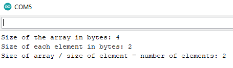
sizeof(pumpPins) is not the number of elements of the array, it's the size of the array in memory. So to get the number of elements, you need to divide that by the size of an element, sizeof(pumpPins) / sizeof(pumpPins[0]).
Some test code:
int myArray[] = {2, 3};

void setup() {
  Serial.begin(9600);
  Serial.print("Size of the array in bytes: ");
  Serial.println(sizeof(myArray));
  Serial.print("Size of each element in bytes: ");
  Serial.println(sizeof(myArray[0]));
  Serial.print("Size of array / size of element = number of elements: ");
  Serial.println(sizeof(myArray) / sizeof(myArray[0]));
}

void loop() {}
My take is that they both do the same job (which I think is emptying) but one runs by itself for 30s and if necessary then the other one cuts in to give more oomph. (It remembers which pump ran first last time and runs the other one first next time, presumably for wear balancing.)
edit: What I'm struggling to understand is exactly what the switches (as proxies for level sensors) actually do. Not sure if one's at the top and one at the bottom, or what? @retcon can we see a diagram of the proposed installation please?
Interesting assignment and nice diagram kinda explaining it except for details.
I am curious about how this assignment was communicated to the student(s). Something might have been lost in @retcon's expression of the problem, woukd it be possible to publish on this forum in this thread the assignment as you received it?
My hope is the the actual assignment would answer many questions. Maybe close examination of the code attempt(s) and diagram would answer, maybe not…
Here's how I would draw it. (It's not clear from your diagram what happens after the alarm comes on, where does it go next, how does it get out of that, so for now that's a ??? mark below.)
This would be straight-foward to code in a few cases of a switch... case.
if the water level reaches high one pump will start to pump out
if the level does not reach low wthin about 30 seconds, the second pump will come into action. if the level reaches low before 30 seconds the pumping should stop.
the pumps will stop when low is detected..
to give even loading of the pumps they are to be used alternately, on one pump cycle P1 starts first and P2 is the 'back up' then on once cycle P2 will start first and P1 is the 'back up'
You're right and I think I was staring at it for too long and breaking it down to these questions properly has helped.
Going to break it down a bit more and look at it using switch cases.
My hastily scribbled state diagram is more or less equivalent to @shetland_siren's prettier version, and stalls with the same question.
In my rendering, Alarm is raised but not as a separate state, more like a side condition. The state is still "both pumps operating, tank not empty" and the same remaining question, um, remains.
What to do if the tank hasn't emptied, the alarm is wailing away and the pumps are operating?
What happens if the tank does finally empty in this circumstance?
Any questions like that that you don't answer before you write the code will in fact get answered when you run it, they might not be the right answers however.
Is anyone making a little tank farm with sensors and pumps so you can play with it for real? Just curious.
Unfortunately no tank farm with the sensors or pumps to check how it works for real, at the moment I'm running it through just using some LEDs to proxy each of the outputs.
though I'm trying to get my head around how to structure the switch case statement, where do I define the variable for the switch itself would this be best to define it as its own function? or is it a case of looking at the variable within each statement?
so I would have 4 cases which outline what happens within each of the 4 switch states?
Thanks for the help guys, starting to feel a little out of my depth with this one
Well when the pumps kick in, you'll be high and dry.
Don't be intimidated, these are well travelled paths.
Google
traffic lights state machine arduino
and read a few of the articles.
The major structure is usually just a switch/case with the cases being one-to-one with the ovals in a diagram like @shetland_siren drew.
IDLE, RUN1, RUN2, ALARM
perhaps using an enum. Enumerated variable type to give the cases nice names.
Eevery time you loop(), which in a program like this would be very frequently, check the sensing switches and get the current time in millis() right away.
Then being in one state or another, each case can use the switches you read, and see what time has elapsed, which two things will inform turning on or off pumps as well as transitioning from state to the next appropriate state.
Many times through the loop the conditions and elapsed time will mean no action needs be taken, like while waiting for 30 seconds to pass or for a sensor to go dry.
It can be a bit tricky, but once you get to the Aha! moment you will have learnt a very good technique for getting some mileage out of these tiny processors.