U8glib wiring Arduino Pro Mini and SSD1306 128x64 OLED display

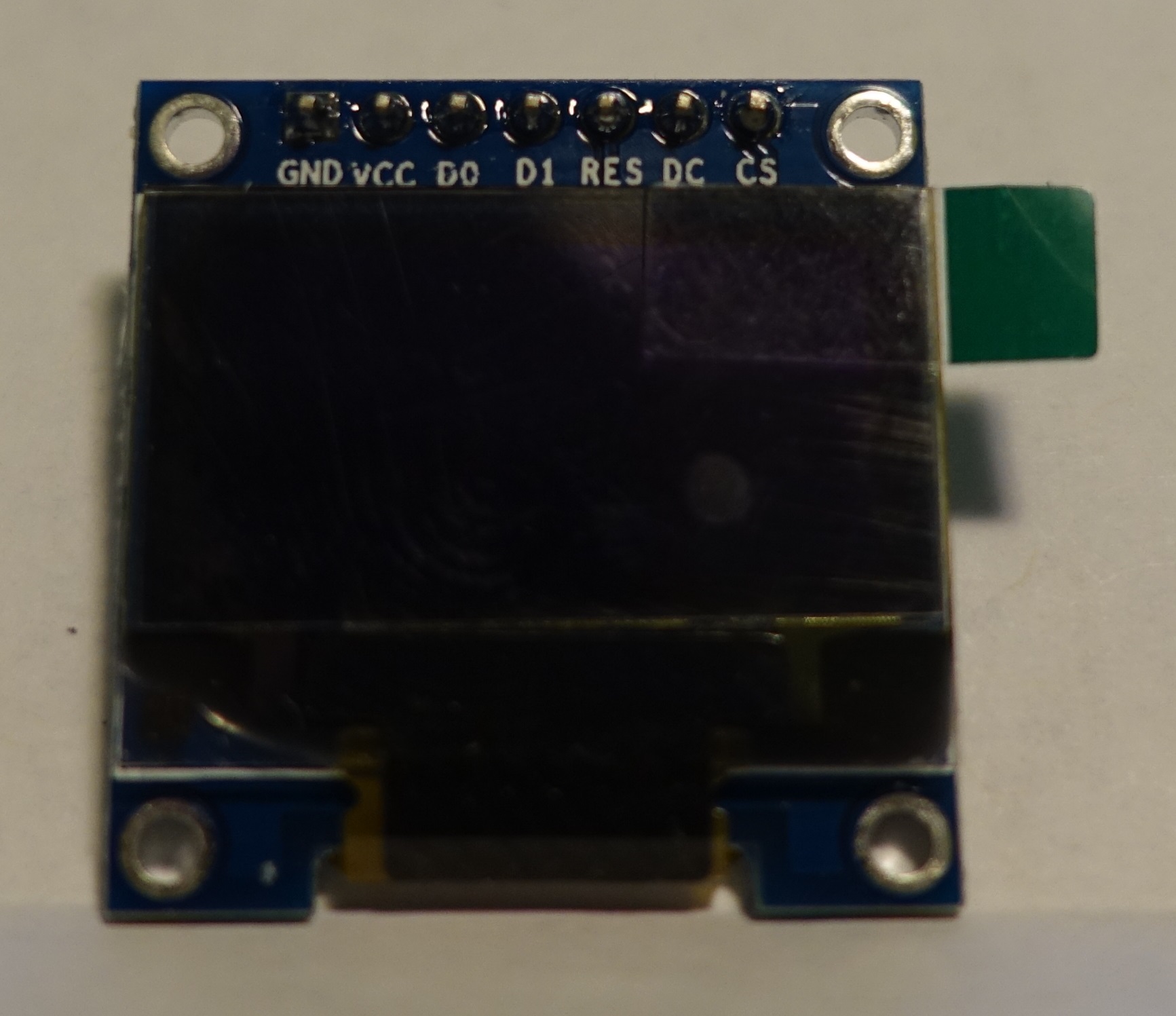
I have a cheap SSD1306 128x64 OLED display with these 6 pins: GND, VCC, SCL, SDA, RST, D/C

I tried using U8glib with it all drivers listed, but I'm making a mistake somewhere with wiring. The display is not dead (yet :slight_smile: ). It worked with Adafruit SSD1306 library software SPI out of the box, with these settings:

#define OLED_MOSI   9
#define OLED_CLK   10
#define OLED_DC    11
#define OLED_CS    12
#define OLED_RESET 13
Adafruit_SSD1306 display(OLED_MOSI, OLED_CLK, OLED_DC, OLED_RESET, OLED_CS);

U8glib drivers that sould work

//U8GLIB_SSD1306_128X64 u8g(13, 11, 10, 9);	// SW SPI Com: SCK = 13, MOSI = 11, CS = 10, A0 = 9
//U8GLIB_SSD1306_128X64 u8g(4, 5, 6, 7);	// SW SPI Com: SCK = 4, MOSI = 5, CS = 6, A0 = 7 (new white HalTec OLED)
//U8GLIB_SSD1306_128X64 u8g(10, 9);		// HW SPI Com: CS = 10, A0 = 9 (Hardware Pins are  SCK = 13 and MOSI = 11)
//U8GLIB_SSD1306_128X64 u8g(U8G_I2C_OPT_NONE|U8G_I2C_OPT_DEV_0);	// I2C / TWI 
//U8GLIB_SSD1306_128X64 u8g(U8G_I2C_OPT_DEV_0|U8G_I2C_OPT_NO_ACK|U8G_I2C_OPT_FAST);	// Fast I2C / TWI 
//U8GLIB_SSD1306_128X64 u8g(U8G_I2C_OPT_NO_ACK);	// Display which does not send AC
//U8GLIB_SSD1306_ADAFRUIT_128X64 u8g(13, 11, 10, 9);	// SW SPI Com: SCK = 13, MOSI = 11, CS = 10, A0 = 9
//U8GLIB_SSD1306_ADAFRUIT_128X64 u8g(10, 9);		// HW SPI Com: CS = 10, A0 = 9 (Hardware Pins are  SCK = 13 and MOSI = 11)

How do I wire this display? Which pins I need to connect to SCK and A0?

Thanks.

SCK = OLED_CLK = SCL
A0 = OLED_DC = D/C

Oliver

I'm having no luck with a similar display. It has 7 pins:

GND VCC D0 D1 RES DC CS

I can connect with the Adafruit example with 4 wire SPI however I can not get it to work with I2C.

The back of the board is clearly marked with the 3 options

  1. I2C
  2. 3 wire SPI
  3. 4 Wire SPI

...and I can see that it is set-up for 4 wire SPI as default. I've moved the SMD resistors to match

the requirements but can get no display at all.

The G8lcd library seems to be clear on which pins to use for SPI but I can not find a reference to the pins required for I2C.

Olikraus - you say that...

SCK = OLED_CLK = SCL
A0 = OLED_DC = D/C

A0 (I take it this is Analogue Pin 0 on the Arduino), but where is the SCK pin on the Arduino???

Attached are 2 photos of the OLED in question! Any help much appreciated

Hi

A0 and SCK are the names for the pins in the U8glib constructor. A0 means address line 0 and is identical to the pin named D/C.
A0 has nothing to do with Analog pin 0 (excause for the confusion): You can use any digital pin. if you have a working setup with the Adafriut lib in this way:

#define OLED_MOSI   9
#define OLED_CLK   10
#define OLED_DC    11
#define OLED_CS    12
#define OLED_RESET 13

Then the u8glib constructor will be:
U8GLIB_SSD1306_128X64 u8g(10, 9, 12, 11, 13); // SW SPI Com: SCK = 10, MOSI = 9, CS = 12, A0 = 11, RST = 13

Oliver

Ok, the issue was the RESET pin which needs to be added as the 5th argument in constructor. In my case pin 13. Here's what worked on Arduino Pro Mini. (Note that I don't have the CS pin on my display, so the pin 12 in the constructor below is not actually used)

//U8GLIB_SSD1306_ADAFRUIT_128X64 u8g(13, 11, 10, 9);  // SW SPI Com: SCK = 13, MOSI = 11, CS = 10, A0 = 9
U8GLIB_SSD1306_ADAFRUIT_128X64 u8g(10, 9, 12, 11, 13);  // SW SPI Com: SCK = 13, MOSI = 11, CS = 10, A0 = 9

Pin numbers are based on example from Adafruit SSD1306 lib (see the first post)

EDIT:
@Joss: Oliver was faster :slight_smile:

hello_oliver.jpg

Nice, thanks,
Oliver

Hi, and thanks to Bit388 and Oliver - that certainly fills in a bit of information on the SPI connections. However I am tring to get the display connected to the I2C and I don't know which pins to use either on the OLED or the Arduino.

The constructor says:

//U8GLIB_SSD1306_128X64 u8g(U8G_I2C_OPT_DEV_0|U8G_I2C_OPT_NO_ACK|U8G_I2C_OPT_FAST); // Fast I2C

but it doesnt say which pins?

My apologies for hijacking this thread (which was a question on SPI) and turn it into a question about I2C I hope you will forgive me :o

In fact I'd like to get this display connected to an ESP8266-01 (now I find I'm in the wrong Forum Ha Ha!!) so if you have any experience of this I'd appreciate it.

Regards

Joss

Joss:
In fact I'd like to get this display connected to an ESP8266-01 (now I find I'm in the wrong Forum Ha Ha!!) so if you have any experience of this I'd appreciate it.

U8glib will not work on ESP.

I have a similar 1.3 ' oled configurable for 3SPI, 4SPI and I2C. I use it with I2C, SDA@D1 and SCL@D0 , Vcc and Gnd ,no other connections .
I have it working without a library, but can only show text , it also can handle OLED's with SH1106 controllers.
you can find 2 projects here: All projects of co sto | Hackaday.io

Joss:
Hi, and thanks to Bit388 and Oliver - that certainly fills in a bit of information on the SPI connections. However I am tring to get the display connected to the I2C and I don't know which pins to use either on the OLED or the Arduino.

The constructor says:

//U8GLIB_SSD1306_128X64 u8g(U8G_I2C_OPT_DEV_0|U8G_I2C_OPT_NO_ACK|U8G_I2C_OPT_FAST); // Fast I2C

but it doesnt say which pins?

U8glib supports the hardware I2C pins of your controller. These pins are hard wired to some of the pins. Look into the description of your board. I2C pins should be listed there.

Oliver

ok again thanks for the responses - I'm actually still trying to get it working on the Arduino Nano first then move onto the ESP. So to answer my own question from your replies then if I am connecting to the Nano I will need to use Pins A4 & A5.

As cartoonist says the G8lcd library will not work with the ESP8266-01 as there no I2C pins brought out onto the header (if they even exist)

Joss:
As cartoonist says the G8lcd library will not work with the ESP8266-01 as there no I2C pins brought out onto the header (if they even exist)

You do not seem to know the ESP very well.
I2C pins are pin-definable on that chip and for the ESP-01 you MUST use pin0 & pin2. (works excellent)

The reason why the U8Glib does not work with the ESP modules is because it generates compile-errors, hopefully Oliver will some day fix that so that this wonderful library is compatible with the ESP8266 chip ....

Hi

I have no idea what the ESP8266 is or what kind of error messages are produced for this device together with u8glib. However i am currently in the migration process for u8glib from google code to github. Code is already in github and I will be happy to add external pull requests on this topic.

New u8glib location: GitHub - olikraus/u8glib: Arduino Monochrom Graphics Library for LCDs and OLEDs

Oliver

I have no(t yet) experience with pull-requests on github, i will study that.
So in short (off-topic) post it here.:

The ESP8266 is a SOC 'system on chip'. It has 802.11 b/g/n WiFi, tcp/ip stack, uart, SPI, I2C, ADC, 80/160 Mhz clock. A highly integrated 32bit CPU in a small package, modules are completed with a minimum of 256kB flashmemory and a PCB/ceramic WiFi antenna and/or U.FL connector. Modules are sold in many variations from a few upto max 16 GPIO pins. The module_size is not much bigger than the nail of a thumb and the price is less than 5 $/€. Programmable from within the Arduino IDE with the Arduino-ESP-addon. GitHub - esp8266/Arduino: ESP8266 core for Arduino . The IDE sees it as just another Arduino compatible board.

The errormessages in IDE 1.6.5 with the HelloWorld sketch are these:

Arduino: 1.6.5 (Linux), Board: "Generic ESP8266 Module, 80 MHz, 115200, 512K (64K SPIFFS)"
from HelloWorld.ino:42:
~ ~ /u8g.h:115:0: warning: "PROGMEM" redefined [enabled by default]
#define PROGMEM
^
from HelloWorld.ino:42:
~ ~ /cores/esp8266/pgmspace.h:15:0: note: this is the location of the previous definition
#define PROGMEM ICACHE_RODATA_ATTR
^
~ ~ /HelloWorld.cpp.elf section .rodata' will not fit in region dram0_0_seg'
~ ~ /HelloWorld.cpp.elf section .bss' is not within region dram0_0_seg'
~ ~ /HelloWorld.cpp.elf section .text' will not fit in region iram1_0_seg'
~ ~ /HelloWorld.cpp.elf section .bss' is not within region dram0_0_seg'

collect2: error: ld returned 1 exit status
Error compiling.

Hmmm.Thanks for the information, but fixing this will not be that easy. At least not without access to this board.

Oliver

cartoonist:
You do not seem to know the ESP very well.
I2C pins are pin-definable on that chip and for the ESP-01 you MUST use pin0 & pin2. (works excellent)

The reason why the U8Glib does not work with the ESP modules is because it generates compile-errors, hopefully Oliver will some day fix that so that this wonderful library is compatible with the ESP8266 chip ....

You are right I'm on a steep learning curve with the ESP family. At present I'm really just copying projects and making tweaks here and there. I particularly like this one:

blog.squix.ch/2015/06/esp8266-weather-station-v2-code.html

...which I have working with both ESP-01 and ESP -12. The I2C pins are set (chosen by the user) inside the main program. My initial question was so obvious to me but not clearly communicated was that it is usual for the pins to be noted somewhere in a program and it was confusing for me to see no such reference in the construtor with the u8glib library. Oivers response threw me a bit as it suggested to me that the I2C must be "hard wired" which they are clearly not in the ESP8266 (as you stated)

I can echo your statement about the usefulness of the u8glib and the hope that it will be ported at some sage for the ESP boards. Thanks Oliver!

I have never made a "Pull request" - is this a request for changes to the software?

Hi

Porting u8glib to a new architecture is not too difficult, however it requires some problems to get solved:

  • Communication to ports, SPI and I2C subsystem of the target controller
  • Linker side emovement of unused code and data
  • Clearly isolatinge specific code parts from the other specific code parts

The prefered way to do this, is to clone the github library of u8glib, apply and test the modifications. After this, sending back the code to me via pull request. I will then do a review and integrate the code into the main library.

I am still in the transition phase of moving u8glib to githib. There is not much time to work on any functional improvements for u8glib. :frowning:

Oliver

olikraus:
Hmmm.Thanks for the information, but fixing this will not be that easy. At least not without access to this board.

Oliver

If you sent me a P.M. with your address i will send you a breadboard friendly ESP-07 module with a set of extra long female pinheaders.

Porting u8glib to a new architecture is not too difficult,

That sounds promising. Maybe in a not so far future people will be able to use U8Glib on the ESP8266.
I could try to make modifications in the source but i would not know where to start. The errormessages must give me a clue but a message like '#define PROGMEM ICACHE_RODATA_ATTR' is almost like greek to me

ok, i have ordered some of these ESP8266. Not sure when i will have time to work on this. Shiping will also take a 4 to 5 weeks.

Oliver

olikraus:
ok, i have ordered some of these ESP8266. Not sure when i will have time to work on this. Shiping will also take a 4 to 5 weeks.

Oliver

Cool :sunglasses:

Oliver,

I studied the errormessages from the HelloWorld example (which I had shortened a bit) a little more in depth.
They all seem to point to files inside the Arduino-ESP8266-addon.

this one:
"/home/costo/.arduino15/packages/esp8266/hardware/esp8266/1.6.4-673-g8cd3697/cores/esp8266/pgmspace.h:15:0: note: this is the location of the previous definition
#define PROGMEM ICACHE_RODATA_ATTR"

and the other 3 one's point to this part of the addOn:
"/home/costo/.arduino15/packages/esp8266/tools/xtensa-lx106-elf-gcc/1.20.0-26-gb404fb9/bin/../lib/gcc/xtensa-lx106-elf/4.8.2/../../../../xtensa-lx106-elf/bin/ld:"

So now I doubt hat the solution is to modify the U8Glib source but to me it looks that the way ESP8266-AddOn handles the ProgMem is the source of the errormessages.
That would mean that the developer(s) of the add-on have to solve this issue.

Maybe this message is helpfull for you.