I'm using Arduino mega 2560 to receive some data from dspic30f3011 via RS232(UART), and on the Arduino side I use RS232-TTL to fit in the right voltage.
#include <Wire.h>

unsigned int RxTemp2[9];

byte buffer[9];

unsigned int RS,RRS,RCO,RS1,RS2,RS3,RS4,RRS1,RRS2,RCO1,RCO2,RCO3,RCO4;

void setup() {
Serial.begin(9600);
Serial3.begin(9600);

}

void loop() {
  int x;

  while(!Serial3.available()>0){}
delay(100);
x=Serial3.available();
Serial.println(x);
//Serial.println(Serial3.read());
Serial3.readBytes(buffer,9);
buffer[9] = RxTemp2[9];
if(buffer[0]==0xEE && buffer[7]==0xEE && buffer[8]==0xEE){

Serial.println("Refspeed:");
Serial.print(buffer[1], HEX);
Serial.println(buffer[2], HEX);
RRS1=buffer[1]<<8;
RRS2=buffer[2]&0xFF;
RRS=RRS1+RRS2;

Serial.println("Speed:");
Serial.print(buffer[3], HEX);
Serial.println(buffer[4], HEX);
RS1=buffer[3]<<8;
RS2=buffer[4]&0xFF;
RS=RS1+RS2;

Serial.println("Controloutput:");
Serial.print(buffer[5], HEX);
Serial.println(buffer[6], HEX);
RCO1=buffer[5]<<8;
RCO2=buffer[6]&0xFF;
RCO=RCO1+RCO2;

}

else{
for (int x = 0; x < sizeof(buffer) / sizeof(buffer[0]); x++)
{
buffer[x] = 0;
}
Serial.println("no data!");
}
Serial.println(RRS);
Serial.println(RS);
Serial.println(RCO);
}
This is my PIC code:
void __attribute__((__interrupt__)) _T4Interrupt (void)
{
	IFS1bits.T4IF = 0;	// Cleat interrupt flag
	TXINX=0;

	Txdata[0]=0xEE;
	Txdata[1]=(RefSpeed>>8);
	Txdata[2]=(RefSpeed&(256-1));
	Txdata[3]=(Speed>>8);//(ControlOutput>>8);
	Txdata[4]=(Speed&(256-1));//(ControlOutput&(256-1));
	Txdata[5]=(ControlOutput>>8);
	Txdata[6]=(ControlOutput&(256-1));
	Txdata[7]=0xEE;
	Txdata[8]=0xEE;
	while(TXINX<9)
	WriteUART2(Txdata[TXINX++]);
	return;
}

void WriteUART2 (unsigned int data)
{
    U2TXREG = data;
    while(!U2STAbits.TRMT){}
}
My questions are:
gcjr
July 7, 2021, 1:52pm
2
why not simply
    if (Serial3.available())
        Serial.print (Serial3.read());
if need to read binary data, consider Automess.ino
I try your advice, and it become:
Maybe the data didn't send to Arduino successfully...
gcjr
July 7, 2021, 2:06pm
4
can you post how you interpreted my advice?
(the infamous "i did what you said")
void loop() {

x=Serial3.available();
Serial.println(x);

if(Serial3.available()){

delay(400);
Serial.println(Serial3.read());
Serial3.readBytes(buffer,9);
RxTemp2[9]=buffer[9];
if(RxTemp2[0]==0xEE && RxTemp2[7]==0xEE && RxTemp2[8]==0xEE){

Serial.println("Refspeed:");
Serial.print(RxTemp2[1], HEX);
Serial.println(RxTemp2[2], HEX);
RRS1=RxTemp2[1]<<8;
RRS2=RxTemp2[2]&0xFF;
RRS=RRS1+RRS2;

Serial.println("Speed:");
Serial.print(RxTemp2[3], HEX);
Serial.println(RxTemp2[4], HEX);
RS1=RxTemp2[3]<<8;
RS2=RxTemp2[4]&0xFF;
RS=RS1+RS2;

Serial.println("Controloutput:");
Serial.print(RxTemp2[5], HEX);
Serial.println(RxTemp2[6], HEX);
RCO1=RxTemp2[5]<<8;
RCO2=RxTemp2[6]&0xFF;
RCO=RCO1+RCO2;
Serial.println(RRS);
Serial.println(RS);
Serial.println(RCO);
}
  }
else{
for (int x = 0; x < sizeof(RxTemp2) / sizeof(RxTemp2[0]); x++)
{
RxTemp2[x] = 0;
}
Serial.println("no data!");
}

}
The result is:
Thank you for your reply!!
gcjr
July 7, 2021, 3:05pm
6
there was really no output on the very first iteration?
        Serial3.readBytes(buffer,9);
        RxTemp2[9]=buffer[9];
you realize that above simply copies the 10th byte from buffer[] to RxTemp[]?
maybe you should only try to read 9 bytes if there are 9 bytes available
    if (9 <= Serial3.available()) {
        Serial3.readBytes (RxTemp,9);
I measured the waveform from TTL, which is between RS232 and Arduino.
Kinda weird...
When it says "no data!" it means that one or more of those comparisons failed. Perhaps you should print out the value of the 9 bytes in buffer before you look for the pattern.
  Serial3.readBytes(buffer,9);
  for (int i=0; i<9; i++)
  {
    Serial.print(" 0x")
    Serial.print(buffer[i], HEX);
  }
  Serial.println();
That will let you see what you actually received.
gcjr
July 7, 2021, 5:14pm
9
tony_lai:
Kinda weird...
time to show a wiring diagram and indicate where you measured
A power supply with 48V drives the motor control circuit, and a converter reduced the voltage to 5~15V for PIC.
48V---->converter---->5V---->PIC--->MAX232---RS232---MAX232--->TTL------------->Arduino----->laptop
About the common ground, the circuit I'm using in PIC is Figure 1, the RS232 wiring is Figure 2, and the MAX232 to TTL is Figure 3.
I think that that is what you have to sort out; doesn't look like a TTL signal to me.
What do the PIC signals look like? What do the RS232 signals look like?
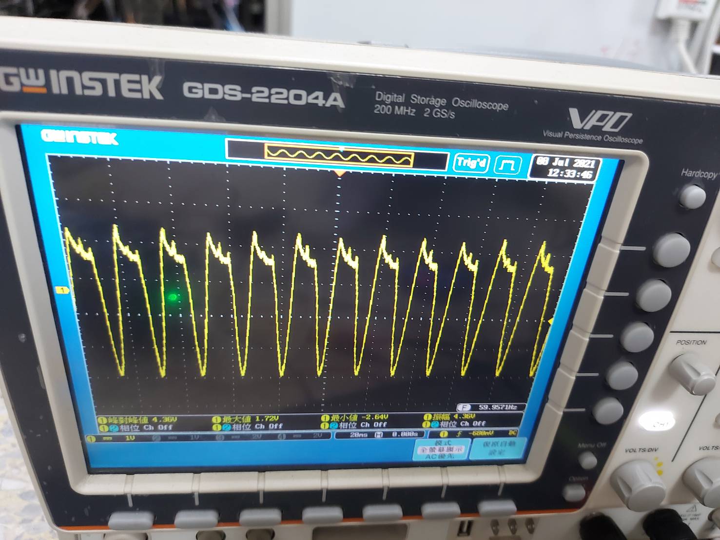
The Tx signal from PIC is:
The signal from Max232 is:
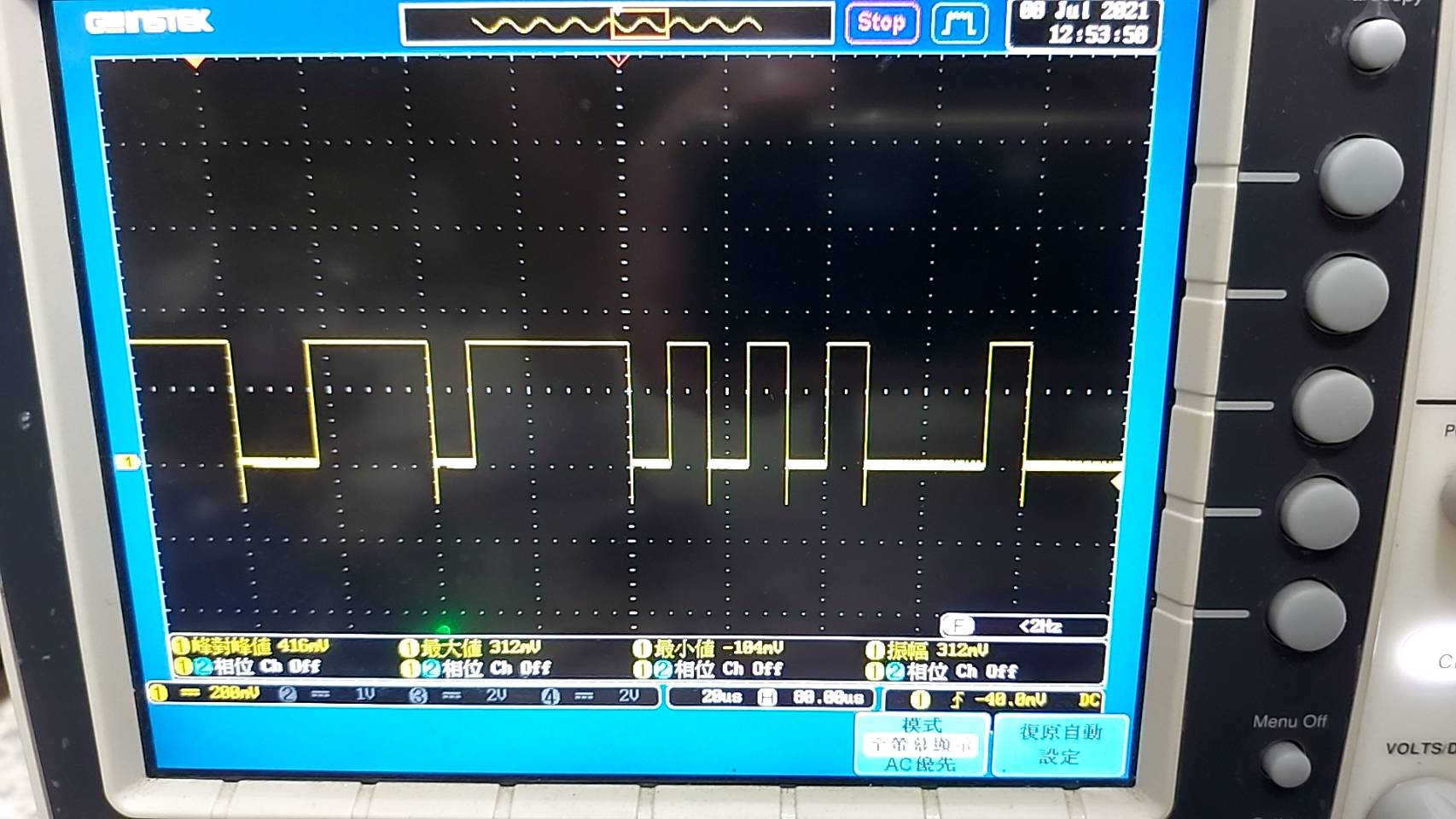
The signal from TTL is:
gcjr
July 8, 2021, 10:35am
13
is there a max232 on the board circles in blue?
tony_lai:
Figure31107×1477 174 KB
There is a MAX3232 between RS232 to TTL on the board.
gcjr
July 9, 2021, 9:53am
15
tony_lai:
presumably the RX of the mega is connected to the TTL out of the max232 and same for TX
it is the RX and TX connections between the max232s, between the DB9 connectors, either in the cable or that short connector with the orange band, that are swapped
tony_lai:
Figure31107×1477 174 KB
dlloyd
July 10, 2021, 2:47pm
16
I agree ... looks like you have a null modem adapter where possibly the data and the handshake lines are crossed.
system
November 7, 2021, 2:47pm
17
This topic was automatically closed 120 days after the last reply. New replies are no longer allowed.