Hello, I want to read and write data from the CNC machine with the RS485 converter in the image. Can anyone share sample code?
try a web search for arduino rs485 you will get plenty of links plus sample code
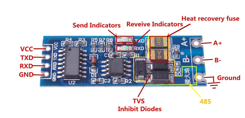
you may find information and sample code for a different RS485 breakout module, e.g.rs-485-arduino-quick-primer, which had two extra pins RE and DE to enable the transmitter and receiver - you can ignore these
a USB-RS485 dongle for a PC s useful for testing and debugging code
do you have information on the protocol used by the CNC machine?
what Arduino are you planning to use? recommend you use one with hardware serial ports, e.g. Mega, ESP32, etc

the board in the first image should be easier to use as you don't have the pins RE and DE to enable the transmitter and receiver - I assume that the internal logic of the first board sorts this out for you
just connect TXD and RXD to your host microctroller and you should be able to transmit and receive RS485 data with a simple program
what arduino are you using?

try this code
// ESP8266 SoftwareSerial
// https://circuits4you.com/2016/12/14/software-serial-esp8266/

#include <SoftwareSerial.h>

// pins Rx GPIO14 (D5) and Tx GPIO 12 (D6)
SoftwareSerial swSer(14, 12);

void setup() {
  Serial.begin(115200);   //Initialize hardware serial with baudrate of 115200
  swSer.begin(115200);    //Initialize software serial with baudrate of 115200
  Serial.println("\nESP8266 Software serial test started");
}

void loop() {
  while (swSer.available() > 0) {  //wait for data at software serial
    Serial.write(swSer.read()); //Send data recived from software serial to hardware serial
  }
  while (Serial.available() > 0) { //wait for data at hardware serial
    swSer.write(Serial.read());     //send data recived from hardware serial to software serial
  }
}
connect
ESP8266 Rx GPIO14 (D5) to RS485 TXD
ESP8266 Tx GPIO 12 (D6) to RS485 RXD
any idea what is the baudrate of the CDC machine? the above is 115200baud
you should be able to type on the serial monitor to send data over the RS485 link and see the response
9600 - 8 - Even - 1
set the Serial1 baudrate to 9600, e.g.
swSer.begin(9600, SERIAL_8E1); //Initialize software serial with baudrate of9600
Can I see all the data coming from the machine? In my previous work, I could only see the parameters I set.
You should be able to see any reply from your CNC machine.
You need to know the serial communication parameters such as baud rate in order to successfully communicate with the CNC machine.
What communications protocol is used? You need to know this in order to interrogate your CNC machine and understand the response you get from it.
Post a link to the user guide.
Also, is the image in post #5 your board? Are RXD2 & TXD2 available. If so, you could use a hardware serial port.
if you know the protocol you send a command and should be able to see the response
Edit: checking the ESP8266softwareserial documentation the baud rate setting should be
swSer.begin(9600, SWSERIAL_8E1); //Initialize software serial with baudrate of9600
yes my device
The use of an RS485 interface may suggest a protocol such as Modbus. You need to provide a link to the user guide or photos of the relevant pages from a paper manual if that is the case.
These codes are for the converter in the second (4 pin) picture I took. I actually want to convert this code to the converter (RX-TX) one in the first image I shot.
The code I used before:
#include <ESP8266WiFi.h>
#include <SPI.h>
#include <ModbusRTU.h>
#include <SoftwareSerial.h>

char str0[6];

SoftwareSerial S(0, 4);
ModbusRTU mb;

bool cb(Modbus::ResultCode event, uint16_t transactionId, void* data) { // Callback to monitor errors
  if (event != Modbus::EX_SUCCESS) {
    Serial.print("Request result: 0x");
    Serial.print(event, HEX);
  }
  return true;
}

void setup() {
Serial.begin(9600);
  S.begin(9600, SWSERIAL_8E1);
  mb.begin(&S, 16); // RE/DE connected to D0 of ESP8266
  mb.master();
}
uint16_t val0[1];

void loop() {
       if (!mb.slave()) {
    mb.readHreg(2, 8501, val0, 1, cb); // Slave id is 1 and register address is 3926 and
    //we are reading 2 bytes from the register and saving in val
    while(mb.slave()) { // Check if transaction is active
      mb.task();
      delay(100);
    }
      Serial.println("Register Values ");
      Serial.println(val0[0]);
      dtostrf(val0[0], 0, 0, str0);
        yield();
     }

            if (!mb.slave()) {
    mb.readHreg(2, 3240, val0, 1, cb); // Slave id is 1 and register address is 3926 and
    //we are reading 2 bytes from the register and saving in val
    while(mb.slave()) { // Check if transaction is active
      mb.task();
      delay(100);
    }
      Serial.println("Register Values ");
      Serial.println(val0[0]);
      dtostrf(val0[0], 0, 0, str0);
        yield();
     }
}
Assuming that the code works for the 4 pin RS485 board, then going from a board with RE & DE signals to an auto switching board should not need any code modifications.
I told you already in
that with modbus you have to request a register and the amount of values you want to read starting from that register.
To read more information you send another request with the next register and the amount of values.
You have to repeat this for all information you want.
Furthermore I told you already to post the datasheet of your device describing the protocol you want to read.
If you would do so - someone could help you.