Hello this is my first post, just getting started with Arduino and loving it!
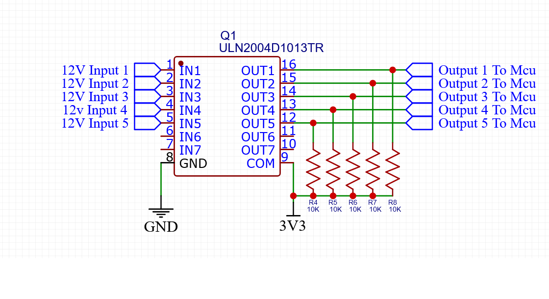
I have a question about interfacing 12v automotive signals into my MKR-Zero and I came up with this schematic and bread boarded it and seems to be working ok. My question is has anyone else done this and does it look like a viable way to do this?
The resistors are pull up to 3V3 I just drew them in there for example of how it would work.
Other than that it should be ok to do this ? Its strange that a google search for using it in this way didn't find anything and I'm worried that there was a reason lol
cd74HC4050 powered from 3.3V will do the same without needing the pullups. https://www.digikey.com/product-detail/en/texas-instruments/CD74HC4050E/296-9213-5-ND/376792
"The ’HC4049 and ’HC4050 are fabricated with high-speed silicon gate technology. They have a modified input protection structure that enables these parts to be usedas logic level translators which convert high-level logic to a lowlevel logic while operating off the low-level logic supply. For example, 15-V input pulse levels can be down-converted to 0-V to 5-V logic levels. The modified input protection structure protects the input from negative electrostatic discharge."