Hi... I was wondering if anyone could help me with the code when connecting an LCD and ultrasonic sensor...
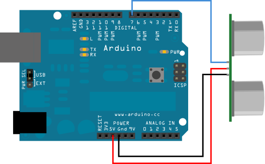
I wired up the ultrasonic sensor on an arduino duemilanove just like the image in the link below.
I then wired up a parralel LCD display screen just like in the link below..
After uploading the code for the lcd display, the lcd works perfectly ( but obviously the ultrasonic sensor isnt working) . In addition, when uploading the code for the ultrasonic sensor, the ultrasonic sensor works perfectly (on the serial monitor) but the lcd is obviously not working..
The problem i am having is that i do not know how to combine the two codes to make the reading of the ultrasonic sensor work on the LCD display . Can somebody please help me with this issue.. I have posted the seperate codes for the ultrasonic sensor and the lcd below :
CODE FOR ULTRASONIC SENSOR :
/* Ping))) Sensor
This sketch reads a PING))) ultrasonic rangefinder and returns the
distance to the closest object in range. To do this, it sends a pulse
to the sensor to initiate a reading, then listens for a pulse
to return. The length of the returning pulse is proportional to
the distance of the object from the sensor.
The circuit:
- +V connection of the PING))) attached to +5V
- GND connection of the PING))) attached to ground
- SIG connection of the PING))) attached to digital pin 7
created 3 Nov 2008
by David A. Mellis
modified 30 Aug 2011
by Tom Igoe
This example code is in the public domain.
*/
// this constant won't change. It's the pin number
// of the sensor's output:
const int pingPin = 7;
void setup() {
   // initialize serial communication:
   Serial.begin(9600);
 }
void loop()
{
// establish variables for duration of the ping,
// and the distance result in inches and centimeters:
long duration, inches, cm;
// The PING))) is triggered by a HIGH pulse of 2 or more microseconds.
// Give a short LOW pulse beforehand to ensure a clean HIGH pulse:
pinMode(pingPin, OUTPUT);
digitalWrite(pingPin, LOW);
delayMicroseconds(2);
digitalWrite(pingPin, HIGH);
delayMicroseconds(5);
digitalWrite(pingPin, LOW);
// The same pin is used to read the signal from the PING))): a HIGH
// pulse whose duration is the time (in microseconds) from the sending
// of the ping to the reception of its echo off of an object.
pinMode(pingPin, INPUT);
duration = pulseIn(pingPin, HIGH);
// convert the time into a distance
inches = microsecondsToInches(duration);
cm = microsecondsToCentimeters(duration);
Serial.print(inches);
Serial.print("in, ");
Serial.print(cm);
Serial.print("cm");
Serial.println();
delay(100);
}
long microsecondsToInches(long microseconds)
{
// According to Parallax's datasheet for the PING))), there are
// 73.746 microseconds per inch (i.e. sound travels at 1130 feet per
// second). This gives the distance travelled by the ping, outbound
// and return, so we divide by 2 to get the distance of the obstacle.
// See: http://www.parallax.com/dl/docs/prod/acc/28015-PING-v1.3.pdf
return microseconds / 74 / 2;
}
long microsecondsToCentimeters(long microseconds)
{
// The speed of sound is 340 m/s or 29 microseconds per centimeter.
// The ping travels out and back, so to find the distance of the
// object we take half of the distance travelled.
return microseconds / 29 / 2;
}
CODE FOR LCD :
Code
/*
LiquidCrystal Library - Hello World
Demonstrates the use a 16x2 LCD display. The LiquidCrystal
library works with all LCD displays that are compatible with the
Hitachi HD44780 driver. There are many of them out there, and you
can usually tell them by the 16-pin interface.
This sketch prints "Hello World!" to the LCD
and shows the time.
The circuit:
- LCD RS pin to digital pin 12
- LCD Enable pin to digital pin 11
- LCD D4 pin to digital pin 5
- LCD D5 pin to digital pin 4
- LCD D6 pin to digital pin 3
- LCD D7 pin to digital pin 2
- LCD R/W pin to ground
- 10K resistor:
- ends to +5V and ground
- wiper to LCD VO pin (pin 3)
Library originally added 18 Apr 2008
by David A. Mellis
library modified 5 Jul 2009
by Limor Fried (http://www.ladyada.net)
example added 9 Jul 2009
by Tom Igoe
modified 22 Nov 2010
by Tom Igoe
This example code is in the public domain.
*/
// include the library code:
#include <LiquidCrystal.h>
// initialize the library with the numbers of the interface pins
LiquidCrystal lcd(12, 11, 5, 4, 3, 2);
void setup() {
   // set up the LCD's number of columns and rows:
  lcd.begin(16, 2);
   // Print a message to the LCD.
   lcd.print("hello, world!");
 }
void loop() {
// set the cursor to column 0, line 1
// (note: line 1 is the second row, since counting begins with 0):
lcd.setCursor(0, 1);
// print the number of seconds since reset:
lcd.print(millis()/1000);
}