I don't know how to make a code without copying and pasting From anywhere from anyone. So i am early beginner in Arduino Uno, ESP32 Wi-Fi. Please some one can help me then it will be good for me.
I am currently working on Ultrasonic Water Level Indicator Using ESP32 Wi-Fi based module device so i don't know the exact code for the same.
I moved your topic to an appropriate forum category @parth3698.
In the future, please take some time to pick the forum category that best suits the subject of your topic. There is an "About the _____ category" topic at the top of each category that explains its purpose.
Okay sir i am trying to learn it and tries make us perfect but it's my priority basis first project for which i will launch this project as a product device into the market so if can you please help me with this then it will be good for me.
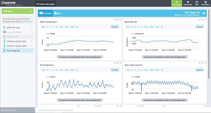
some time back I built a river monitoring system using The Things UNO with a BMP280 temperature/pressure sensor, a SR04M ultrasonic transducer and a DS18B20 DallasTemperature sensor uploading data over LoRaWAN to the myDevices/cayenne desktop
I was reading the sensors and uploading data every 10 minutes
you can see the river is tidal – rise and fall of about 10cm
this is a test program I used for SR04M ultrasonic sensor - you may need to change pins to suit the ESP32
// Arduino - simple sonar distance demonstrator using ultrasocic transducer
//  trigger connected to pin 12 and echo to pin 13

// the setup function runs once when you press reset or power the board
void setup() {
  //pinMode(11, OUTPUT);  // initialise IO pins
  pinMode(12, OUTPUT);  // trigger pulse
  pinMode(11, INPUT);   // echo pulse
  Serial.begin(115200);
  //digitalWrite(11, HIGH);   // power, high voltage level
}

// the loop function runs over and over again forever
void loop() {
    // trigger pulse high approx 10 microseconds
    digitalWrite(12, HIGH);   // HIGH is the voltage level
    digitalWrite(12, HIGH);
    digitalWrite(12, HIGH);


   // now trigger low
    digitalWrite(12, LOW);    // voltage LOW
    // wait for echo pulse to go high
    while(!digitalRead(11)) ;
    // start timer
    unsigned long StartTime = micros();
    // wait for end of echo pulse (goes low)
    while(digitalRead(11)) ;
    unsigned long CurrentTime = micros();
    // calculate length of echo pulse in microseconds
    unsigned long HighLevelTime = CurrentTime - StartTime;
    // calculate distance High level time * vecocity (340M/sec)/2
    float distance=HighLevelTime*340.0/20000;  // in cm
    Serial.print("ADRM1 Time ");
    Serial.print(HighLevelTime, DEC);
    Serial.print(" microseconds, distance ");
    Serial.print(distance, 2);
    Serial.println(" cm");
    delay(1000);              // short delay before next pulse
}
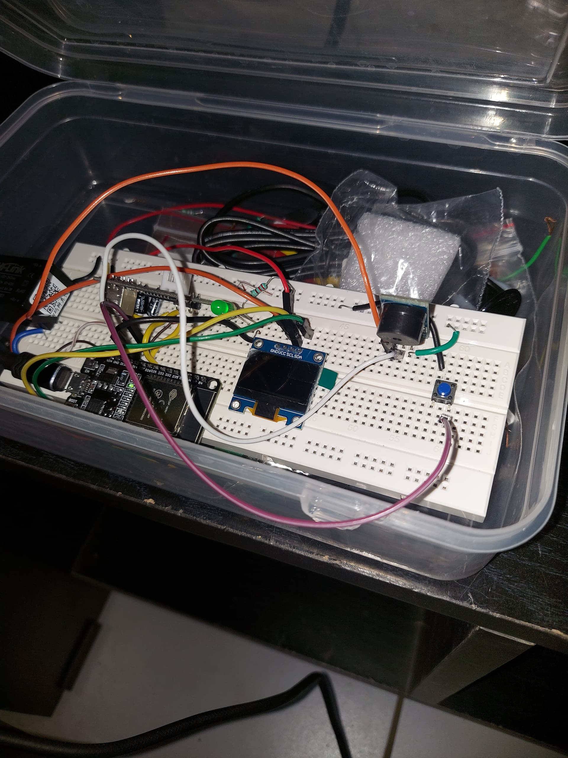
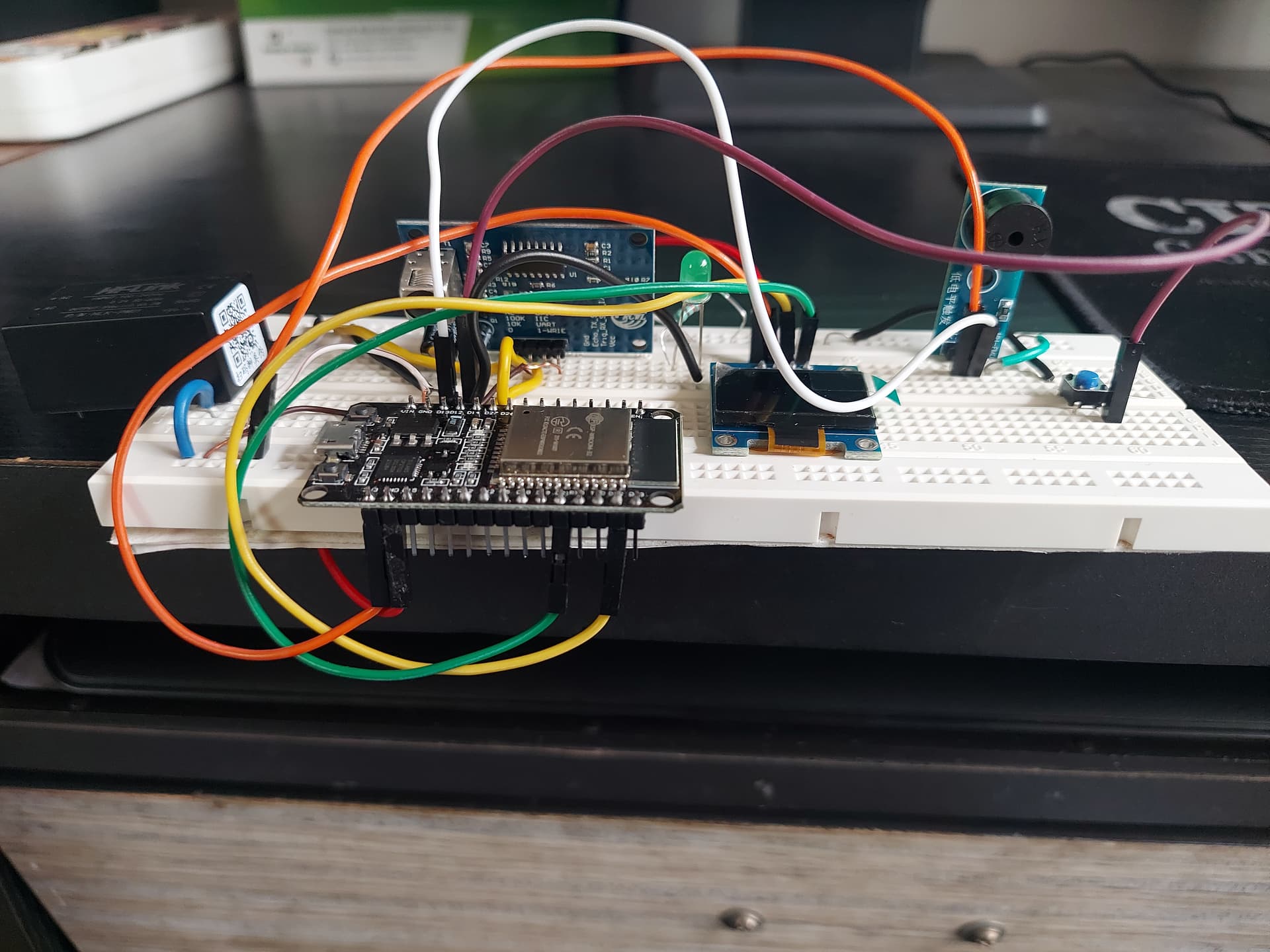
This are my circuit diagram connection as per given diagram so please try to understand this and if you want more accurate and clear picture of circuit diagram i can give you
I am sorry to say that unless you learn the basics then you are in no position to launch an Arduino based product unless you pay someone to write the code and support it afterwards