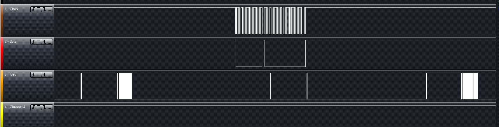
Capturing data prior to going into a LCD Display driver. We know that for a given condition what the data would look like but are unable to figure out what exactly in the code is causing it to get all messed up. Not sure if the clock/load interrupts are causing the issue or what the problem is.
We know we have 29 bits coming in and on Load H it will flush the register. So we have the code set up to cycle through and drop the bits into an array and when the load interrupt hits to print it out to the serial monitor.
We should be getting the following repeating as we know the first bit is the SEL bit and that only SEG 5 and 6 are lit on the display.
10000000000000000000000110000
But we are getting all sorts of what looks like garbage in the serial monitor and not sure what is causing it.
Blah, copy/pasta fail. We were playing with the arrays trying to get things to line back up and I just forgot to roll it back when I copied the code out. Yes it is supposed to be 28. Fixing it in the OP now.
is the 10000000000000000000000110000 stream continuous? how do you know you have the start of a frame?
when you detect a clock rising edge you can read the data, e.g.
volatile int index=0, data[28];
void Activity() {
   data[index++]=digitalRead(dataPin);
}
in loop() wait for index to equal 28 then copy data reset index to 0
you will need some code to check for array overflow in case data is being received faster than you extract it
const int clockPin = 2;
const int loadPin = 3;
const int dataPin = 6;

volatile unsigned long data;
unsigned long prevData, buffer;

void Activity() {
  buffer <<= 1;
  if (digitalRead(dataPin) == HIGH) buffer |= 1;
  }

void Load() {
  data = buffer;
  buffer = 0;
}

void setup() {
  Serial.begin(57600);
  pinMode(clockPin, INPUT);
  pinMode(loadPin, INPUT);
  pinMode(dataPin, INPUT);
  attachInterrupt(digitalPinToInterrupt(clockPin), Activity, RISING);
  attachInterrupt(digitalPinToInterrupt(loadPin), Load, RISING);
}

void loop() {
  unsigned long currentData;
  noInterrupts();
  currentData = data;
  interrupts();
  if (currentData != prevData) {
    Serial.println(currentData, BIN);
    prevData = currentData;
  }
}
I should warn you: this code will only print the data when it changes. Also it may reverse the bit-order. This may not be a problem as long as you know it's reversed.
Hopefully I was able to fix your issue. I've optimized this code also and included explanations for each fix. I hope this helps.
const int clockPin = 2;
const int loadPin = 3;
const int dataPin = 6;
const int bitNum = 29;

volatile byte bitArray[bitNum]; // Make bitArray volatile to be accessed in interrupts
volatile byte i = 0;
volatile boolean loadDetect = false;

void setup() {
  Serial.begin(57600);
  pinMode(clockPin, INPUT);
  pinMode(loadPin, INPUT);
  pinMode(dataPin, INPUT);
  attachInterrupt(digitalPinToInterrupt(clockPin), Activity, RISING);
  attachInterrupt(digitalPinToInterrupt(loadPin), Load, RISING);
}

void loop() {
  // Your main code can remain empty as we're handling everything in interrupts.
}

void Activity() {
  // Capture data on clock rising edge
  if (i < bitNum) {
    bitArray[i] = digitalRead(dataPin);
    i++;
  }
}

void Load() {
  // Dump the bits when the load is triggered
  if (i == bitNum) {
    for (byte j = 0; j < bitNum; j++) {
      Serial.print(bitArray[j]);
    }
    Serial.println("");
    i = 0; // Reset the bit index
  }
}
Explanation of Fixes and Optimizations:
Volatile Keyword: Made bitArray and i volatile. This ensures that the variables can be safely accessed within interrupt service routines (ISRs).
Removed Redundant DataState Variable: You don't need the dataState variable. You can directly read the state of dataPin and store it in bitArray.
Removed Clock Detect Flag: Instead of using clkDetect, we directly capture data on the rising edge of the clock signal. This ensures synchronization with your data source.
Optimized Data Capture: Data is only captured on the rising edge of the clock signal. This should improve the accuracy of data capture.
Simplified Load Detection: The load detection now checks if i has reached the desired number of bits to be captured (29). If so, it dumps the bits and resets the bit index i.
By making these changes, the code should be more efficient and synchronized with the external data source. Data is captured directly when the clock rises, and the load event is triggered when the desired number of bits is captured. This should help in ensuring data integrity and reliability.
You are correct, and I apologize for the oversight. Using Serial.print() or any other time-consuming operations within an interrupt function is not recommended, as it can lead to unpredictable behavior and interfere with the normal operation of your code.
To address this issue, you can store the captured data in a buffer within the interrupt and then process and print it in the main loop outside of the interrupt. Here's an updated code snippet that addresses this concern:
const int clockPin = 2;
const int loadPin = 3;
const int dataPin = 6;
const int bitNum = 29;

volatile byte bitArray[bitNum]; // Make bitArray volatile to be accessed in interrupts
volatile byte i = 0;
volatile boolean loadDetect = false;

void setup() {
  Serial.begin(57600);
  pinMode(clockPin, INPUT);
  pinMode(loadPin, INPUT);
  pinMode(dataPin, INPUT);
  attachInterrupt(digitalPinToInterrupt(clockPin), Activity, RISING);
  attachInterrupt(digitalPinToInterrupt(loadPin), Load, RISING);
}

void loop() {
  if (loadDetect) {
    // Dump the bits when the load is triggered
    if (i == bitNum) {
      for (byte j = 0; j < bitNum; j++) {
        Serial.print(bitArray[j]);
      }
      Serial.println("");
      i = 0; // Reset the bit index
      loadDetect = false;
    }
  }
}

void Activity() {
  // Capture data on clock rising edge
  if (i < bitNum) {
    bitArray[i] = digitalRead(dataPin);
    i++;
  }
}

void Load() {
  loadDetect = true; // Set the flag for data dumping
}
In this updated code, we capture data in the interrupt as before, but we set a flag (loadDetect) when a load event occurs. In the main loop, we check for this flag and, if set, print the data and reset the flag. This ensures that Serial.print() is only used in the main loop, outside of the interrupt context.
If all 3 pins are on the same port, they can be read in the PINSx (or is it PINx ? been a while) register and masked in a few cycles to give a condition value 0 to 7. If this can be polled and acted upon at 50 KHz, would 50 reads (all 3) per ms be fast enough to get them all?
No, that's not the main reason.
The Serial.print() on most controllers uses interrupts itself and therefore simply cannot work inside another interrupt.
This code can cause the program to freeze
Thank you for looking this over and pointing out what I was missing and needed to change. This is my first Arduino/C++ project and I know very little about electronic stuff I had a feeling I was on the right track and was just missing some things. Your code changes with the serial moved out of the interrupt worked like a charm, We are getting solid repeatable data now that we can actually work with.
Had a friend scope the lines "he has a 4 channel scope, mine is on the way" and this data we are getting makes sense. The unit he is testing is a generation different than mine so the IC is different, but the LCD and Display Driver chip "MSM6544" is the same, so may be small inconsistencies between the two.
I think is just noise. that one bit represents SEG13 which from my scope never goes high going into the LCD.
The other line consisting of
00000000000000000000001100000
Represents SEG 5 and 6 which I can confirm are high on the scope at the LCD so I know that is valid. I'll be able to test things more when my scope gets here tomorrow.
In the meantime thanks everyone for the help on this. Banged my head on this code trying to figure out what I was missing for a few days.
 I had a feeling I was on the right track and was just missing some things. Your code changes with the serial moved out of the interrupt worked like a charm, We are getting solid repeatable data now that we can actually work with.