I was following this tutorial and hello world tutorial from aurdino what ever I do lcd is not displaying content.
Some times it displays single line with block and some times two lines with blocks and sometimes none.
Arduino LCD Screen Only Displays Blocks.._gaMTIwMjI1MDc3Ni4xNzQxMTc1ODMw*_ga_NEXN8H46L5*MTc0MTE3NTgyOS4xLjAuMTc0MTE3NTgyOS4wLjAuMTUzMzk2NzMzMQ..
I followed above url and still I can't see a thing.Of I connect vo to ground i can see blocks on top row
Please post schematics.
Check the connections to and from the breadboard, eventually change the strips used to another strip.

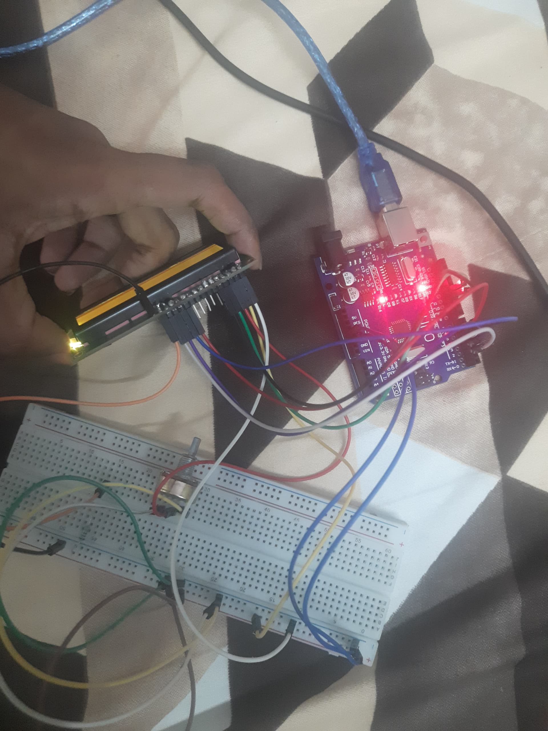
I have connect gnd to gnd
Vcc to 5 v
Vo to a 200 ohn resistor
Rs to 7
Rw to gnd
D4,d5,d6,d7 to 9,10,11,12
@Railroader
Can u help me test any potential soldering issues thank you
What 7 ? You have d7 to 12.
Yes @mikedb 7pin on the aurdino could u please suggest me a schema to make my lcd work?

#include <LiquidCrystal.h>

LiquidCrystal lcd(7, 8, 9, 10, 11, 12);

void setup(){
  lcd.begin(16, 2);
  lcd.print("hello, world!");
}

void loop(){

}
Where is Pin 8 > Enable?
Ops connected it now but still no results on the display
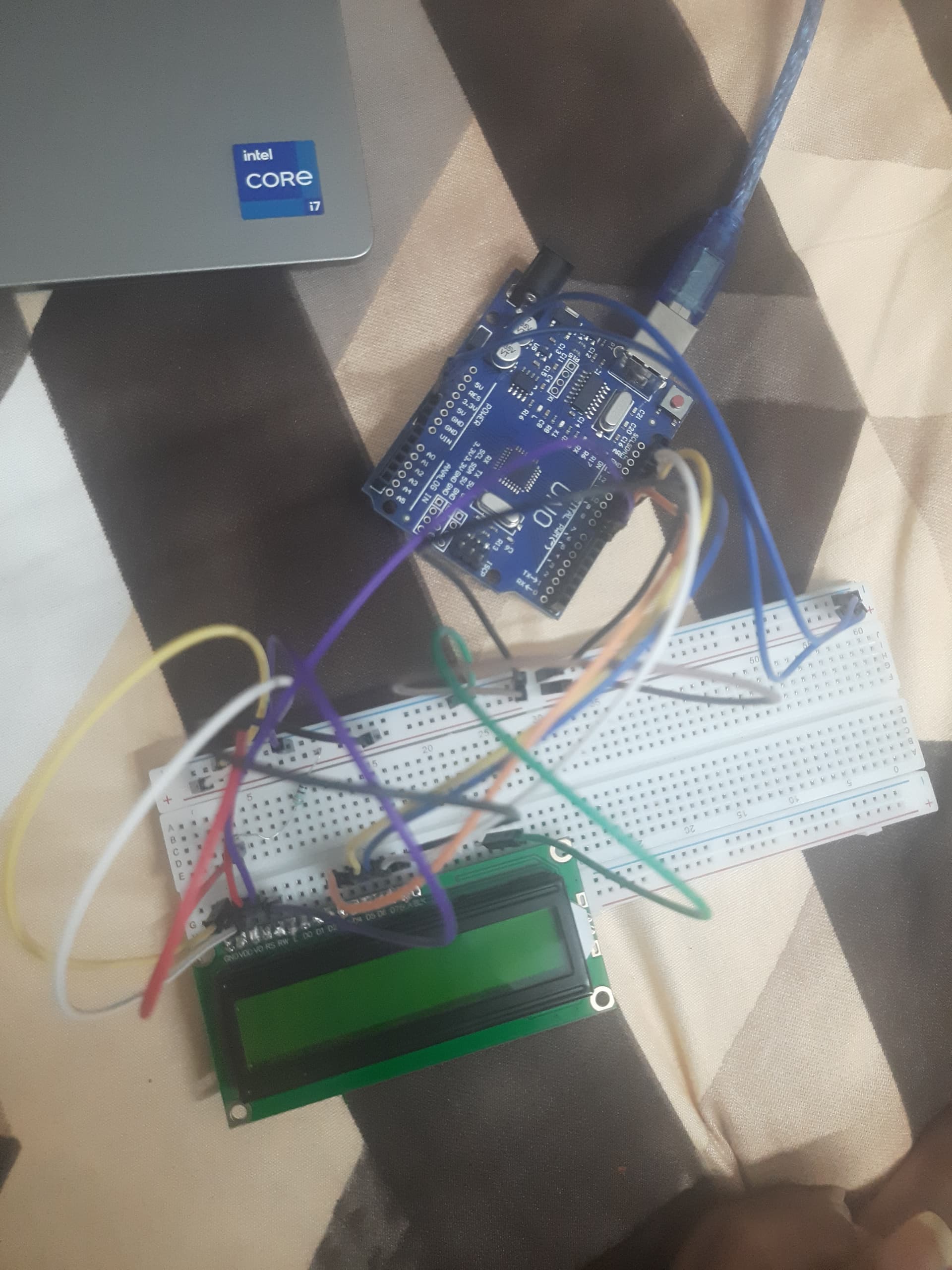
check your breadboard.
It seems the power rails (red and blue ones) are not connected from left to right but are interrupted in the middle of the board.
I connected left to right using jumping wires @noiasca

Does Vo go to Gnd , use a bigger resistor like 1k , the blocks must be just visible.
Your soldering on the Lcd does not look good maybe dry joints.
Yes @mikedb when I put vo to ground i can see blocks and hello world printed
?? Then what is the problem??
I mean it's working now I don't know how thank you @mikedb Ispent whole night for this,![]() most happiest now:grinning_face_with_smiling_eyes:
most happiest now:grinning_face_with_smiling_eyes:
Good to to know.
By the way I @mikedb I need to see it through side to get view of i view straight i only see blocks how can I fix it?
Use a bigger value resistor between Vo and Gnd .
Also use that variable resistor in your previous pics just connect between Vo and Gnd , then adjust the contrast.
Edit. Use center and 1 side pin of the variable resistor.
1 Like
You need to resolder the header pins to that display board, some of those solder joints look awful.