Understanding ISR

Hi,

My setup is as follows:
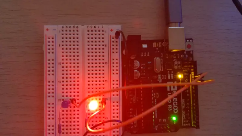
Board: Arduino Uno
Compiler: Clang 11 (compiled from source)
I do not use the Arduino library (Arduino.h, etc...)

I am having a bit of trouble understanding why some code in an ISR seems to not be executed.

Here is a code snippet of an ISR that works as intended:

ISR(TIMER1_COMPA)
{
    portb portb{};
    portb.PORTB4.flip();
    portb.PORTB5.flip();
}

This ISR gets called every second and switch on and off two LEDs. This goes on until the board is powered off, perfect!

Now if I add an if statement to this ISR it does not seem to get executed. The ISR now looks like this:

volatile char stop_counter = 0;
ISR(TIMER1_COMPA)
{
    char counter = stop_counter;
    if(counter < 16)
    {
        portb portb{};
        portb.PORTB4.flip();
        portb.PORTB5.flip();
    }
    stop_counter = counter + 1;
}

The type portb is a wrapper around a class containing a volatile reference to the address of portb (0x25 as per the datasheet, see p. 72 - 13.4.2 PORTB – The Port B Data Register).

Now, I know the code I wrote does not work because the LEDs should stop blinking after 16 seconds but they do not. They carry on blinking until the board is powered off.

I also know the code for the if statement is not removed by the compiler since when I use avr-objdump to see the emitted instructions I can see the instructions for the comparison.

This is the avr-objdump output (I have added the comments):

; CORE SETUP + STACK MANAGEMENT
  a6:   78 94           sei
  a8:   0f 92           push    r0
  aa:   1f 92           push    r1
  ac:   0f b6           in      r0, 0x3f        ; 63
  ae:   0f 92           push    r0
  b0:   00 24           eor     r0, r0
; USER STACK MANAGEMENT
  b2:   2f 93           push    r18
  b4:   8f 93           push    r24
  b6:   9f 93           push    r25
; BRANCH
  b8:   80 91 60 00     lds     r24, 0x0060     ; 0x800060 <__DATA_REGION_ORIGIN__>
  bc:   80 31           cpi     r24, 0x10       ; 16
  be:   44 f4           brge    .+16            ; 0xd0 <__vector_11+0x2a>
; FLIP PORTB BIT #4
  c0:   90 e1           ldi     r25, 0x10       ; 16
  c2:   25 b1           in      r18, 0x05       ; 5
  c4:   29 27           eor     r18, r25
  c6:   25 b9           out     0x05, r18       ; 5
; FLIP PORTB BIT #5
  c8:   90 e2           ldi     r25, 0x20       ; 32
  ca:   25 b1           in      r18, 0x05       ; 5
  cc:   29 27           eor     r18, r25
  ce:   25 b9           out     0x05, r18       ; 5
; BRANCH LANDING SPOT IF STOP_COUNTER >= 16
  d0:   83 95           inc     r24
  d2:   80 93 60 00     sts     0x0060, r24     ; 0x800060 <__DATA_REGION_ORIGIN__>
; USER CODE STACK MANAGEMENT
  d6:   9f 91           pop     r25
  d8:   8f 91           pop     r24
  da:   2f 91           pop     r18
; CORE CLEAN UP + STACK MANAGEMENT
  dc:   0f 90           pop     r0
  de:   0f be           out     0x3f, r0        ; 63
  e0:   1f 90           pop     r1
  e2:   0f 90           pop     r0
  e4:   18 95           reti

I know the code has a few other issues and I know I should not put too much code in an ISR however, these are not my concerns right now.

I would love it if someone could help me understand why the code seems to be ignored?
As I understand it, an ISR is a bog-standard function at a specific address therefore I assumed that an if statement would not be an issue obviously, I was wrong.

If you need more information, I will be happy to provide more.

Cheers!

Where’s your code to assign the ISR ?
Is it set up properly ?

ISR is a macro that sets up the ISR properly. I know it is setup correctly since the LEDs do toggle on and off every second with the ISR v1.

The second version of the ISR is setup like the first one, the only difference is the if statement added and the global volatile variable stop_counter.

In my code, I have either the first version or the second version but not both at the same time.

I see you copy stop_counter to counter for manipulation within the ISR, but it seems you don't copy counter back to stop_counter at the end of the ISR?

Also, why model it as a char and not an int, uint8_t etc?

I used char just because it is test code. I first tried to use an if statement to do something different and when it did not work I simplified my code to the minimum to see what was the issue.

As for your first point, the last line of the ISR is assigning counter + 1 back to stop_counter.

What's the value of OCR1A?

stop_counter is defined as int8_t and will overflow at 0x7F. Is the phenomenon that you are observing a crash and restart or simply an overflow.

Did you mean to put this:

in the 'if' block

Not sure how I managed to miss that :wink:

OCR1A is set to clock_speed / prescaler_value - 1.
In this particular configuration:
clock_speed = 16,000,000Hz.
prescaler_value = 1,024.
OCR1A = 16,000,000 / 1,024 - 1 = 15,624

So OCR1A is set to 15,624.

1 Like

@6v6gt That's a good catch but those were the details I was talking about when I said I knew the code has other issues but they were not my concerns right now.

You are 100% correct that it will overflow but since I set everything to 0 to start with and the ISR only gets called once a second it should stop blinking after 16 seconds have elapsed.

It should then carry on incrementing up until 127 so for another 111 seconds it should not blink since the if statement would be false. Then stop_counter would overflow and go back down to -128 and start blinking again for another 144 seconds until the counter reaches 16 again and then the cycle should continue until the board is powered off.

Once again, you are correct, I could have put the statement stop_counter = counter + 1 inside the if to prevent the overflow scenario however whether I put this statement inside or outside the 'if' block, I should still see a period without blinking LEDs.

What I experience is 'as if' the 'if' block were not there, the LEDs blink once every second until the board is powered off.

@anon35827816 Haha, no worries! I cannot remember the number of times I missed stuff as well :stuck_out_tongue:

In order to express my problem more clearly, I have changed the code to this:

volatile uint8_t stop_counter{0};
ISR(TIMER1_COMPA)
{
    uint8_t counter{stop_counter};
    if(counter < uint8_t{2})
    {
        portb portb{};
        portb.PORTB4.flip();
        portb.PORTB5.flip();
        stop_counter = counter + uint8_t{1};
    }
}

I have also uploaded a 10s video of what is happening:
isr-issue-blinking-leds

As you can see, after the board has been programmed, the LEDs are flashing for the remainder of the video. However, the video is 10 seconds long and in the modified code above I changed the condition to make the LEDs blink when the counter is less than 2.

I can't explain your problems but you are using some rather odd ways of setting variables and not all the code is visible.

Here is a simple Arduino-less timer sketch using timer 1 and an 'if' statement to toggle the built-in UNO led. Maybe it helps isolate the problem:

// LED pin 13 = PORTB 0x20 ;

ISR(TIMER1_COMPA_vect) { //timer1 interrupt 1Hz toggles pin 13 (LED)
  //generates pulse wave of frequency 1Hz/2 = 0.5Hz (takes two cycles for full wave- toggle high then toggle low)

  static bool toggle1 = false ;
 
  if (toggle1) {
    // digitalWrite(13,HIGH);
    PORTB |= 0x20 ;
    toggle1 = 0;
  }
  else {
    // digitalWrite(13,LOW);
    PORTB &= ~0x20 ;
    toggle1 = 1;
  }
}


int main() {
  //set pins as outputs
  // pinMode(13, OUTPUT);

  DDRB |= 0x20 ;

  cli();//stop interrupts

  //set timer1 interrupt at 1Hz
  TCCR1A = 0;// set entire TCCR1A register to 0
  TCCR1B = 0;// same for TCCR1B
  TCNT1  = 0;//initialize counter value to 0
  // set compare match register for 1hz increments
  OCR1A = 15624;// = (16*10^6) / (1*1024) - 1 (must be <65536)
  // turn on CTC mode
  TCCR1B |= (1 << WGM12);
  // Set CS12 and CS10 bits for 1024 prescaler
  TCCR1B |= (1 << CS12) | (1 << CS10);
  // enable timer compare interrupt
  TIMSK1 |= (1 << OCIE1A);

  sei();//allow interrupts

  while ( 1 ) {
    // loop()
  }

}

Edit:
Full source of original code (but using Arduino features) :

For what it's worth, the disassembly looks correct.

I don't see anything wrong with your code.
It's a bit weird/bad to have an SEI instruction at the beginning of your ISR...

Can you post a complete, compilable source?

Compiler: Clang 11

Hmm. And a disassembly of the complete program?

Could you be running into something sneaky and unrelated to the ISR itself, like having the WDT enabled by fuses causing your CPU to reset in time periods similar to your blinking pattern?

@6v6gt cheers, I took a closer look and I am confident I have set up all the registers correctly for the interrupt.

@Coding_Badly cheers, that's what I thought as well, I guess the issue lies somewhere else :slight_smile:

@westfw Yeah, I see what you mean about the SEI instruction, that allows having nested interrupts, right? That's a good catch, I should be able to easily get rid of it by using the proper attribute on the ISR.

I will set up a Github repo with the code and you won't need to compile clang from the source. I believe since clang 12 AVR is supported out-of-the-box.

This is the full disassembly of the program:

build/blinky:     file format elf32-avr


Disassembly of section .text:

00000000 <__vectors>:
   0:   0c 94 34 00     jmp     0x68    ; 0x68 <__ctors_end>
   4:   0c 94 51 00     jmp     0xa2    ; 0xa2 <__bad_interrupt>
   8:   0c 94 51 00     jmp     0xa2    ; 0xa2 <__bad_interrupt>
   c:   0c 94 51 00     jmp     0xa2    ; 0xa2 <__bad_interrupt>
  10:   0c 94 51 00     jmp     0xa2    ; 0xa2 <__bad_interrupt>
  14:   0c 94 51 00     jmp     0xa2    ; 0xa2 <__bad_interrupt>
  18:   0c 94 51 00     jmp     0xa2    ; 0xa2 <__bad_interrupt>
  1c:   0c 94 51 00     jmp     0xa2    ; 0xa2 <__bad_interrupt>
  20:   0c 94 51 00     jmp     0xa2    ; 0xa2 <__bad_interrupt>
  24:   0c 94 51 00     jmp     0xa2    ; 0xa2 <__bad_interrupt>
  28:   0c 94 51 00     jmp     0xa2    ; 0xa2 <__bad_interrupt>
  2c:   0c 94 53 00     jmp     0xa6    ; 0xa6 <__vector_11>
  30:   0c 94 51 00     jmp     0xa2    ; 0xa2 <__bad_interrupt>
  34:   0c 94 51 00     jmp     0xa2    ; 0xa2 <__bad_interrupt>
  38:   0c 94 51 00     jmp     0xa2    ; 0xa2 <__bad_interrupt>
  3c:   0c 94 51 00     jmp     0xa2    ; 0xa2 <__bad_interrupt>
  40:   0c 94 51 00     jmp     0xa2    ; 0xa2 <__bad_interrupt>
  44:   0c 94 51 00     jmp     0xa2    ; 0xa2 <__bad_interrupt>
  48:   0c 94 51 00     jmp     0xa2    ; 0xa2 <__bad_interrupt>
  4c:   0c 94 51 00     jmp     0xa2    ; 0xa2 <__bad_interrupt>
  50:   0c 94 51 00     jmp     0xa2    ; 0xa2 <__bad_interrupt>
  54:   0c 94 51 00     jmp     0xa2    ; 0xa2 <__bad_interrupt>
  58:   0c 94 51 00     jmp     0xa2    ; 0xa2 <__bad_interrupt>
  5c:   0c 94 51 00     jmp     0xa2    ; 0xa2 <__bad_interrupt>
  60:   0c 94 51 00     jmp     0xa2    ; 0xa2 <__bad_interrupt>
  64:   0c 94 51 00     jmp     0xa2    ; 0xa2 <__bad_interrupt>

00000068 <__ctors_end>:
  68:   11 24           eor     r1, r1
  6a:   1f be           out     0x3f, r1        ; 63
  6c:   cf ef           ldi     r28, 0xFF       ; 255
  6e:   d8 e0           ldi     r29, 0x08       ; 8
  70:   de bf           out     0x3e, r29       ; 62
  72:   cd bf           out     0x3d, r28       ; 61

00000074 <__do_copy_data>:
.L__do_copy_data_start:
        cpi     r26, lo8(__data_end)
        cpc     r27, r17
        brne    .L__do_copy_data_loop
#elif !defined(__AVR_HAVE_ELPMX__) && !defined(__AVR_HAVE_ELPM__)
        ldi     r17, hi8(__data_end)
  74:   10 e0           ldi     r17, 0x00       ; 0
        ldi     r26, lo8(__data_start)
  76:   a0 e6           ldi     r26, 0x60       ; 96
        ldi     r27, hi8(__data_start)
  78:   b0 e0           ldi     r27, 0x00       ; 0
        ldi     r30, lo8(__data_load_start)
  7a:   e8 e4           ldi     r30, 0x48       ; 72
        ldi     r31, hi8(__data_load_start)
  7c:   f1 e0           ldi     r31, 0x01       ; 1
        rjmp    .L__do_copy_data_start
  7e:   02 c0           rjmp    .+4             ; 0x84 <__do_copy_data+0x10>
.L__do_copy_data_loop:
#if defined (__AVR_HAVE_LPMX__)
        lpm     r0, Z+
  80:   05 90           lpm     r0, Z+
#else
        lpm
        adiw    r30, 1
#endif
        st      X+, r0
  82:   0d 92           st      X+, r0
.L__do_copy_data_start:
        cpi     r26, lo8(__data_end)
  84:   a0 36           cpi     r26, 0x60       ; 96
        cpc     r27, r17
  86:   b1 07           cpc     r27, r17
        brne    .L__do_copy_data_loop
  88:   d9 f7           brne    .-10            ; 0x80 <__do_copy_data+0xc>

0000008a <__do_clear_bss>:
/* __do_clear_bss is only necessary if there is anything in .bss section.  */

#ifdef L_clear_bss
        .section .init4,"ax",@progbits
DEFUN __do_clear_bss
        ldi     r18, hi8(__bss_end)
  8a:   20 e0           ldi     r18, 0x00       ; 0
        ldi     r26, lo8(__bss_start)
  8c:   a0 e6           ldi     r26, 0x60       ; 96
        ldi     r27, hi8(__bss_start)
  8e:   b0 e0           ldi     r27, 0x00       ; 0
        rjmp    .do_clear_bss_start
  90:   01 c0           rjmp    .+2             ; 0x94 <.do_clear_bss_start>

00000092 <.do_clear_bss_loop>:
.do_clear_bss_loop:
        st      X+, __zero_reg__
  92:   1d 92           st      X+, r1

00000094 <.do_clear_bss_start>:
.do_clear_bss_start:
        cpi     r26, lo8(__bss_end)
  94:   a1 36           cpi     r26, 0x61       ; 97
        cpc     r27, r18
  96:   b2 07           cpc     r27, r18
        brne    .do_clear_bss_loop
  98:   e1 f7           brne    .-8             ; 0x92 <.do_clear_bss_loop>
  9a:   0e 94 72 00     call    0xe4    ; 0xe4 <main>
  9e:   0c 94 a2 00     jmp     0x144   ; 0x144 <_exit>

000000a2 <__bad_interrupt>:
  a2:   0c 94 00 00     jmp     0       ; 0x0 <__vectors>

000000a6 <__vector_11>:
  a6:   0f 92           push    r0
  a8:   1f 92           push    r1
  aa:   0f b6           in      r0, 0x3f        ; 63
  ac:   0f 92           push    r0
  ae:   00 24           eor     r0, r0
  b0:   2f 93           push    r18
  b2:   8f 93           push    r24
  b4:   9f 93           push    r25
  b6:   80 91 60 00     lds     r24, 0x0060     ; 0x800060 <__DATA_REGION_ORIGIN__>
  ba:   82 30           cpi     r24, 0x02       ; 2
  bc:   58 f4           brcc    .+22            ; 0xd4 <__vector_11+0x2e>
  be:   90 e1           ldi     r25, 0x10       ; 16
  c0:   25 b1           in      r18, 0x05       ; 5
  c2:   29 27           eor     r18, r25
  c4:   25 b9           out     0x05, r18       ; 5
  c6:   90 e2           ldi     r25, 0x20       ; 32
  c8:   25 b1           in      r18, 0x05       ; 5
  ca:   29 27           eor     r18, r25
  cc:   25 b9           out     0x05, r18       ; 5
  ce:   83 95           inc     r24
  d0:   80 93 60 00     sts     0x0060, r24     ; 0x800060 <__DATA_REGION_ORIGIN__>
  d4:   9f 91           pop     r25
  d6:   8f 91           pop     r24
  d8:   2f 91           pop     r18
  da:   0f 90           pop     r0
  dc:   0f be           out     0x3f, r0        ; 63
  de:   1f 90           pop     r1
  e0:   0f 90           pop     r0
  e2:   18 95           reti

000000e4 <main>:
  e4:   8f b7           in      r24, 0x3f       ; 63
  e6:   8f 77           andi    r24, 0x7F       ; 127
  e8:   8f bf           out     0x3f, r24       ; 63
  ea:   80 91 81 00     lds     r24, 0x0081     ; 0x800081 <__bss_end+0x20>
  ee:   88 60           ori     r24, 0x08       ; 8
  f0:   80 93 81 00     sts     0x0081, r24     ; 0x800081 <__bss_end+0x20>
  f4:   80 91 81 00     lds     r24, 0x0081     ; 0x800081 <__bss_end+0x20>
  f8:   81 60           ori     r24, 0x01       ; 1
  fa:   80 93 81 00     sts     0x0081, r24     ; 0x800081 <__bss_end+0x20>
  fe:   80 91 81 00     lds     r24, 0x0081     ; 0x800081 <__bss_end+0x20>
 102:   8d 7f           andi    r24, 0xFD       ; 253
 104:   80 93 81 00     sts     0x0081, r24     ; 0x800081 <__bss_end+0x20>
 108:   80 91 81 00     lds     r24, 0x0081     ; 0x800081 <__bss_end+0x20>
 10c:   84 60           ori     r24, 0x04       ; 4
 10e:   80 93 81 00     sts     0x0081, r24     ; 0x800081 <__bss_end+0x20>
 112:   80 e0           ldi     r24, 0x00       ; 0
 114:   90 e0           ldi     r25, 0x00       ; 0
 116:   90 93 85 00     sts     0x0085, r25     ; 0x800085 <__bss_end+0x24>
 11a:   80 93 84 00     sts     0x0084, r24     ; 0x800084 <__bss_end+0x23>
 11e:   80 91 6f 00     lds     r24, 0x006F     ; 0x80006f <__bss_end+0xe>
 122:   82 60           ori     r24, 0x02       ; 2
 124:   80 93 6f 00     sts     0x006F, r24     ; 0x80006f <__bss_end+0xe>
 128:   87 e9           ldi     r24, 0x97       ; 151
 12a:   9a e3           ldi     r25, 0x3A       ; 58
 12c:   90 93 89 00     sts     0x0089, r25     ; 0x800089 <__bss_end+0x28>
 130:   80 93 88 00     sts     0x0088, r24     ; 0x800088 <__bss_end+0x27>
 134:   8f b7           in      r24, 0x3f       ; 63
 136:   80 68           ori     r24, 0x80       ; 128
 138:   8f bf           out     0x3f, r24       ; 63
 13a:   24 9a           sbi     0x04, 4 ; 4
 13c:   25 9a           sbi     0x04, 5 ; 4
 13e:   2c 98           cbi     0x05, 4 ; 5
 140:   2d 9a           sbi     0x05, 5 ; 5
 142:   ff cf           rjmp    .-2             ; 0x142 <main+0x5e>

00000144 <_exit>:
ENDF _exit

        /* Code from .fini8 ... .fini1 sections inserted by ld script.  */

        .section .fini0,"ax",@progbits
        cli
 144:   f8 94           cli

00000146 <__stop_program>:
__stop_program:
        rjmp    __stop_program
 146:   ff cf           rjmp    .-2             ; 0x146 <__stop_program>

No more SEI instruction at the beginning of the ISR, it's called __vector_11 in case you didn't know :wink:

I have not modified any fuses and when I use the simple version of the ISR (the one without an if statement) I can change the timer interval and the LEDs blink at the rate I set.

Input capture ? We have to see the entire source code.

Edit
TIMER1_COMPA_vect is vector 12 for an ATmega328p

Nah. avr-gcc and the datasheet differ on where they start counting.

Ahh. I have it...

  b6:   80 91 60 00     lds     r24, 0x0060     ; 0x800060 <__DATA_REGION_ORIGIN__>
  ba:   82 30           cpi     r24, 0x02       ; 2
  bc:   58 f4           brcc    .+22            ; 0xd4 <__vector_11+0x2e>
      :
  d0:   80 93 60 00     sts     0x0060, r24     ; 0x800060 <__DATA_REGION_ORIGIN__>

RAM on an ATmega328p starts at 0x100. 0x60 is, um, WDTCSR. (Fortunately (?) most of the bits in WDTCSR are "protected" so your write didn't actually work. If it had, you'd probably have even more mysterious symptoms.)

I suspect you have a bad linker script.

(heh. Having the full source code would not have helped find it!)

3 Likes

Hahaha, nice catch! You are right! Just checked the datasheet.

I am not sure why the linker is not choosing the right address for the data section, I checked the spec file and it seems to indicate the data section should start at 0x100.

That's from the specs-atmega328p file:

 60 *link_data_start:
 61         %{!Tdata:-Tdata 0x800100}

If I understand correctly that's the linker script used.

No matter, I found the options to set it manually.
I compiled, uploaded the program to the board and now it works!!!

Cheers!

I am now a bit worried about what other stuff the linker is going to have an opinion about...

But at least, all is well with the world!

A big thank you to you @westfw and thanks to @chrisknightley @6v6gt @Coding_Badly @lastchancename @anon35827816 for taking the time to help me makes sense of it all!

1 Like

I don't know about the Clang toolchain, but for gcc it looks like the values in device-specs/specs-at* are ignored/overridden by the linker scripts (older device, like the ones included with AS7, don't even have link_data_start defined.
avr8-atmel-3.6.1.495/avr/lib/ldscripts/avr5.x contains:

MEMORY
{
  text   (rx)   : ORIGIN = 0, LENGTH = __TEXT_REGION_LENGTH__
  data   (rw!x) : ORIGIN = 0x800060, LENGTH = __DATA_REGION_LENGTH__

Edit: in other words, linker scripts are NOT the same as the specs files. The linker script can USE values that are defined in the specs file, but it might not...

That was a brilliant piece of analysis.

I might disagree here though:

If the OP had more readily produced a compilable source, someone may just have done a comparative compilation/dump, using the Arduino tool chain, and potentially noticed it.
Anyway, good that it is solved.