Hello everyone.. it's been a long time since I last posted on these forums.
Recently, I opened up an old UPS and found a mechanical relay inside. However, I can't understand how its terminal are connected.
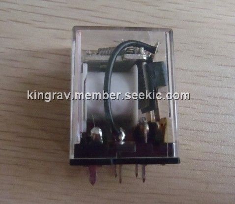
The relay looks somewhat like this: http://www.seekic.com/uploadfile/member_product/18675/201112215424386.jpg
(I can't find an image or the datasheet for the exact model that I have)
On the circuit board on which this relay is mounted, each one of the two terminals of the coil is connected to a terminal of the main power line. I have attached a diagram of the relay. Blue indicates the boundary of the package of the component and red shows the connections made on the circuit board. I think the +ve input is connected to T1, the negative input to T2 and the load accross T5 and T6. However, it seems that this layout does not isolate the coil circuit and the main power circuit. If so, what is the reason for wiring a relay like this?
As shown, the circuit is appears to be pointless. When power is available the relay closes and power passes through to the output terminals. When power is not available, the relay is de-energised and the contacts are open; but in this case there is no power, hence no power is or would be available to the output, irrespective of the relay state. Hence the "pointless" nature of the circuit.
May I suggest you re-examine how the relay is actually connected and redraw your illustration. Alternatively provide a photograph of the actual relay and its connections within the circuit.
I thought the wiring was "pointless" too.. I must have made some mistake in my interpretation in the connections. I'll check and post back. unfortunately, I can't find the data sheet for this relay. The only markings on it's outside say "LB1 DPNO" "Rayex Elec"
When there's mains power then the relay latches and the UPS uses that power from your home circuit. When there's a power outage the relay opens and isolates itself from your home circuit.
An intrinsic rule of backup systems always includes some assurance that you'll not be frying the linesmen that are working on getting the power back up. This relay wiring appears to be a very foolproof way of doing that.
Assuming the mains power comes from the right hand side and the UPS power is on the left. By definition the UPS is "Uninterruptible" which means the system power oscillator is running in synchronous and in parallel with the mains supply. Alternatively it must fire up and come on line in a minimum number of milliseconds, certainly less than 1 cycle of the mains (20 or 17mS). That style of relay will not mechanically drop out in such a short time so it is still closed when the UPS comes on-line following mains failure. Hence the UPS back-feeds the relay and holds it in the energised state.
That is why I state that particular circuit will not function as stated - unless there is some other form of "interrupter" system further to the left of the circuit you show.
But there again, I have been known to be wrong XD XD
Alternatively, if the power comes from the left side and goes to the right side, then the relay coil will hold the contacts shut while the power is present on the left side. When the power on the left side is not present, the coil is deenergised and the contacts open, and will not re-close even if the power on the left side is restored.
For this to be useful, there would have to be something else that we can't see. Like a mechanical switch or lever which will manually reclose the contacts. Or, power applied somehow from the right hand side to re-close the relay.
Hello, I have that same relay, (Reyex lb1 DPNO) And I also scrounge mine from an old UPS. It's looking to me like we have power coming IN/OUT through T1&T2, Which are connected to pine 7&8. Respectively. The current passing through pins 7&8 energize the solenoid, closing the switch. Current goes to pins 5&6 and up the two white wires atop of the switch. with power running through and that switch closed, current passes through the switch to pins 3&4. Pins 3&4 Run straight to your output, T3&T4.
So on your diagram of the relay, you have the two switches running horizontally. Instead the switches would be running vertically in your diagram.
I'm kind of new at writing back on these forums, so if anything is unclear let me know.
Good luck, man!
Correction:
On my previous post above, when talking about "power coming IN/OUT through T1&t2", disregard "OUT."
Excuse me for that, thanks.
Also, for Mahela007:
I was wondering if you also salvaged the power tranny from your UPS. Not sure if it's the same one, but mine came with a toroidal power transformer. What do you have for the outputs on the secondary?
