I'm trying to understand the following flip-flop circuit using 2 NPN transistors as explained in this video :
My apologies for the lengthy post. I noted down all the things that weren't clear to me as questions in this post (Q1,Q2,...)

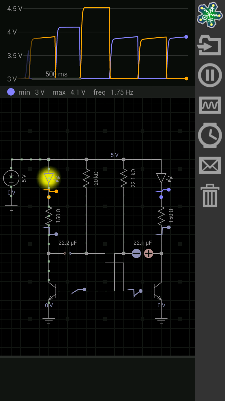
The full circuit diagram:
After applying power, 1 LED (the right one) is lit.
Reasoning here is that this is the case because only 1 transistor is switched on.
In this case the right transistor is turned on causing the right LED to turn on.
Q1 : Am I correct in assuming the LED is lit up because of the following current flowing:
Vcc -> right LED -> right 470ohm -> right Collector -> right Emitter - 100Ohm - GND
- The transistor allows the current to flow through the right LED to ground because it is turned on.
- Had the transistor been turned off, there would have been no path to ground for current wanting to flow trough the right LED).
Q2 : Current that's passing through the right 470ohm resistor can move in 2 ways :
Vcc -> right LED -> right 470ohm -> right transistor Collector -> right transistor Emitter - 100Ohm - GND
Vcc -> right LED -> right 470ohm -> left 10K resistor ->left base transistor.
Wouldn't that second current flow also turn on the left transistor, causing the left LED to turn on ?
This is the flow when the right transistor is turned off, but even when it is turned on, won't you still have current flowing through that path ?
- When the right transistor is turned off, current can only follow the path to the left 10K resistor. (as the transistor is wide open).
- However, when the right transistor is turned on , current can flow through the transistor OR through the left 10k resistor
Q3: I know current is lazy and that it picks the path of least resistance, but in parallel circuits, you always have current going through all branches right ?
- More current would flow into the branch that has less resistance (the transistor being turned on).
- Less current would flow into the branch that has higher resistor (the 10K path from point nr 2).
At 2:50 into the video, it is stated that closing the trigger doesn't change the situation (same LED remains lit) but ....
the 22 microFarad cap is being charged "a little bit more" because the 100ohm resistor is out of the picture.
Q4. Can somebody explain this ? Why is it charging a little bit more, and what exactly is that 100ohm resistor doing.
What happens to the circuit when the 100ohm resistor is out of the picture (by closing the switch).
The capacitor, due to the 100ohm resistor generates a negative voltage pulse on the base of the right transistor, turning it off.
I can understand that a negative voltage on the base would turn off the transistor.
Now that the right transistor is turned off, current can flow like this
Vcc -> right LED -> right 470ohm -> left 10K resistor ->left base transistor.
This results in positive voltage that is applied to base of left transistor , turning it on
Q5: Am I correct in saying that this causes the left LED to light up because we have current flowing through
Vcc -> left LED -> left 470ohm -> left Collector -> left Emitter - 100Ohm - GND
Q6: What happened to the flow of current that caused this transistor to turn on ?
Vcc -> right LED -> right 470ohm -> left 10K resistor -> left base transistor
Is there no current flowing through that path anymore and why ?
Q7: Why don't we see any current branching off using this path
Vcc -> left LED -> left 470ohm -> right 10K resistor -> right base transistor.
Current can go to either the left Collector or the right 10K resistor right ?
Wouldn't that also turn on the right transistor (because a positive voltage would be applied to the right base)
Q8 : Breadboard setup
When I did the setup on a breadboard (same values, but using a 5V supply or a 9V supply), I could simulate the flip-flop as sown in the video , however I did notice 2 other things :
- When one particular LED was turned on , I did notice the other one was also on, albeit very dim
- When I did the "push down" on the switch, I noticed a flicker in the dim LED
Q9 : Practical use
I imagined that a practical use for this would be to have a latching switch with a momentary push button.
The ability to turn something on / off (applying either 5V or 0V to another part of the circuit ) ?
In this case it's obviously a simple LED that is turned on / off, but could you replace that LED + resistor with a complete circuit that you would want to turn on/off using that temporary.
Thanks a lot if you made it this far ! ![]()